Contents Introduction ................................................................................................................................ 4 Understanding VoIP .................................................................................................................... 5 Minimum System Requirements ................................................................................................. 6 Do I need a Micro filter? ...................................................................
Appendix A: Flow Chart of Configuring V100 ............................................................................. 29 V100 PPPoE Mode ............................................................................................................... 29 V100 DHCP Mode ................................................................................................................ 30 V100 Fixed IP Mode ...........................................................................................................
Introduction Thank you for your purchase of NetComm's V100 VoIP ATA (Analogue Telephone Adapter). The V100 ATA is a standards-based communication device that delivers true, next-generation voiceover-IP (VoIP) telephony to residences worldwide. The V100 ATA addresses the needs of smalloffice and home environments and emerging VoIP services by turning your analog phone into an IP device.
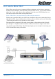
Understanding VoIP You will be able to use your V100 ATA to make and receive calls depending on the type of VoIP plan you subscribe to. In the below examples you have connected the V100 ATA to your standard telephone handset and Broadband Internet Connection, i.e. Cable or DSL service. 1. VoIP Subscriber to VoIP subscriber on the same VoIP network.
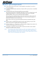
Minimum System Requirements ■ A spare Ethernet port on the router or switch attached to your modem, if you wish to access to the Internet.. ■ A working broadband Internet connection. Consult an ISP if you do not have a broadband connection. ■ A valid SIP VoIP account. There are generally two types available. One type that only provides a VoIP number allows the V100 user to send and recieve calls to and from other VoIP users.
Do I need a Micro filter? Micro filters are used to prevent common telephone equipment, such as phones, answering machines and fax machines, from interfering with your ADSL service. If your ADSL enabled phone line is being used with any other equipment other than your ADSL Modem then you will need to use one Micro filter for each phone device. Note: A Microfilter is not required with a Cable Internet connection.
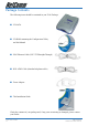
Package Contents The following items should be contained in your V100 Package: ■ V100 ATA ■ CD-ROM containing the Configuration Utility and this Manual ■ RJ45 Ethernet Cable (CAT5 UTP Straight-Through) ■ RJ11 ADSL Cable (Standard telephone cable) ■ Power Adapter ■ This Installation Guide Check the contents of your package and, if any parts are missing or damaged, please contact your Dealer. V100 User Guide 8 YML749Rev1 www.netcomm.com.
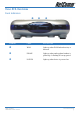
V100 ATA Overview Front Indicators NUMBER LABEL DESCRIPTION WAN Lights up when WAN link and activity is detected. PHONE Lights up when analog phone handset is picked up; Or flashing at boot up period. POWER Lights up when device is powered on. YML749Rev1 www.netcomm.com.
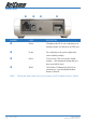
Back Panel NUMBER LABEL DESCRIPTION Phone Telephone jack (RJ-11) for connecting to an analogue phone; also known as an FXS port. Power For connecting to the power adapter that comes with the package. Reset To reset your V100 to its factory default settings. (All customised settings that you have saved will be lost!) WAN 10/100 Base-T Ethernet Jack (RJ-45) for connecting to your Broadband Modem, Router or Switch.
V100 Start Up 1. Ensure that your V100 is powered on, as indicated by the Power LED. 2. WAN LED will light up if an ethernet cable is connected to the WAN port. 3. The Phone LED will begin flashing, indicating that the V100 is booting up. 4. When the phone LED stops flashing, the boot up process has finished. Resetting the V100 ATA to its factory default settings: 1. Ensure that your V100 has completed booting up. 2.
Installing the V100 ATA This section covers the installation of the V100 ATA on your network. Before continuing ... Please ensure you have checked the following requirements: ■ A spare Ethernet port on the router or switch attached to your modem, if you wish to access to the Internet.. ■ A working broadband Internet connection; either Cable or ADSL. Consult an ISP if you do not have a broadband connection. ■ A valid SIP VoIP account. There are generally two types available.
Option A - Ethernet ADSL Internet Connection Connect the V100 ATA to your ADSL modem as illustrated in the following diagram: Figure 1 - Connecting the V100 ATA to an ADSL Router/Modem 1. Connect the Phone socket on the rear of your V100 ATA to an analogue telephone using a RJ-11 cable. 2. Connect the WAN socket on your ATA to one of the LAN ports of your router/switch using a Category 5 cable.
Option B - Optus/Telstra Cable Internet Connection Connect the V100 ATA to your Cable modem as illustrated in the following diagram: Figure 2 - Connecting the V100 ATA to a Cable Modem Note: You also can connect the V100ATA directly to your cable modem. However, in this connection other network devices, such as your PC, cannot share cable modem Internet access. 1. Connect the Phone socket on the rear of your V100 ATA to an analogue telephone using a RJ-11 cable. 2.
Installing the V100 ATA Utility 1. Insert the CD-ROM provided in your package. 2. The following screen will appear automatically. Note: Should the V100 CD not start automatically, you may not have the Autorun feature enabled on your PC. To overcome this, open a Windows Explorer screen, Select the CD-Rom drive into which you have put the V100 CD in and excecute the Autorun.exe file by double clicking on it. The below screen will then appear. 3.
Using the V100 ATA Configuration Utility Once the V100 ATA Configuration Utility has been installed you will see the following window: Status Tab VoIP Phone Number: Your VoIP provider will assign a number. If you are intending to use the V100 ATA in an IP to IP mode (commonly known as Peer-to-Peer) you must configure the V100 ATA with the correct settings. Please refer to the section on Telephone Book Tab for further instructions.
DNS 1: The Domain Name Service that the V100 ATA uses to resolve domain names to IP addresses. This is usually your modem / router. DNS 2: The Domain Name Service that the V100 ATA uses to resolve domain names to IP addresses. This is usually your modem / router. DNS 2 can be a different address to DNS 1 to provide a backup DNS server if DNS 1 fails. MAC Address: The unique hexadecimal hardware address of the V100 ATA's NIC (Network Interface Card). This cannot be modified.
Connection Mode Tab Clicking on the Connection Mode tab brings up the following window: PPPoE: Select this option if your V100 ATA uses PPPoE to authenticate with the modem / router. User name: The PPPoE account username. This is not your VoIP number. This username is issued by your ISP. Password: The PPPoE account password. This is not your VoIP password. This password is issued by your ISP.
IP Address: The unique address of the V100 ATA on your network. Subnet Mask: The subnet mask of your network. Default Gateway: The gateway's address through which the V100 ATA communicates with the Internet. This is usually your modem / router. DNS 1: The Domain Name Service that the V100 ATA uses to resolve domain names to IP addresses. This is usually your modem / router. DNS 2: The Domain Name Service that the V100 ATA uses to resolve domain names to IP addresses.
SIP Tab Clicking on the SIP tab brings up the following window: Local The sub-tab labelled Local has the following sections: ■ Host ■ Phone Configuration ■ Proxy and Registrar Let us take a look at these sections now. Host Max Digits (1-24): Indicates the maximum number of digits (numbers) you can dial using the V100 ATA. Default: 24. Port No.: The port on the host used to communicate with the remote end. Default: 5060. This port can be changed.
Phone Configuration User Name: Your VoIP phone number. Your VoIP provider will assign you this number. If you are not with a VoIP provider, this number is a self-defined number in Peer-to-Peer call mode. (Refer to the section on Telephone Book Tab for instructions. ) Display Name: What the called party sees when you call them. Codec: G.729 is a high compression codec which only occupies 8kbits/ sec, whereas G.711 alaw and G.711 ulaw require 64kbits/sec. We highly recommend you use G.729 instead of G.
Call Forward The sub-tab Call-Forward has the following options: CallForward: You can either enable or disable call forwarding. If enabling call forwarding you can enter a VoIP phone number to forward incoming calls to: User Name: The SIP username (VoIP number) to which calls will be forwarded to (e.g. 09100308). IP Addr.
UnConditional: If enabled, incoming calls will be forwarded to the specified number without ringing on your VoIP phone. If disabled your VoIP phone will ring the specified number of times before being forwarded to the number above. CallForward Rings: Used to set max ring numbers for call forwarding on reply/ answer. Enter number of rings between 1 and 20. Default: 5. YML749Rev1 www.netcomm.com.
STUN Tab Clicking on the STUN tab displays the following: STUN stands for Simple Traveral of UDP over NAT. It is a protocol which enables your IP phone to detect the presence and type of NAT behind which the phone is placed. STUN will allow SIP signalling and bi-directional conversation to successfully traverse a NAT without requiring any configuration changes on the NAT. STUN IP or Domain Name: The STUN server's IP address or domain name usually provided by your service provider.
Telephone Book Tab The Telephone Book should only be used in SIP "non-proxy" mode (Refer to the section on SIP Tab - to configure this setting). With the "Telephone Book" you do not need to subscribe to a VoIP service provider. You will need to obtain the public IP address and SIP outbound address port of the SIP Phone or ATA you wish to communicate with. All this information is required to build a valid phone book entry.
User Name: Enter the username of the person (e.g. Kirstin) that you want to reach. And the remote party must use this username to accept incoming calls. Speed Dial: Enter a speed dial number (e.g. 123). Whenever dialling 123 using your V100 you will be connecting to the Destination IP address on the specified port. Dest IP Address: The IP address of the device to which you want to connect to. Display Name: The name displayed to the person you are calling.
Tool Tab Clicking on the Tool tab displays the following window: System The System sub-tab displays the following options: Save: Saves any changes made to the configuration of the device. Default: Set the device to its default settings. Reboot: Reboot the device. Diagnostic Click on the Diagnostic sub-tab to display the following: IP Address or Host Name: YML749Rev1 www.netcomm.com.au Enter the IP address or host name you wish to test a ping response from. Click Submit to execute the command.
Upgrading the V100's Firmware To upgrade the V100's firmware please download the latest version from the NetComm website. See www.netcomm.com.au. 1. Create a folder on you PC and copy the downloaded file to this folder. 2. Next run your V100 ATA Utility. Select the Upgrade tab. 3. Next type in the location of the firmware upgrade file and its name in 'The Image File' field. Alternativly, you can click on the button with the 3 dots located next to this field and browse your PC for the file’s location. 4.
Appendix A: Flow Chart of Configuring V100 This section covers procedures for configuring V100 in different network scenarios. You might use the following flow charts as reference for your real configuration practice and trouble shooting. V100 PPPoE Mode YML749Rev1 www.netcomm.com.
V100 DHCP Mode V100 User Guide 30 YML749Rev1 www.netcomm.com.
V100 Fixed IP Mode YML749Rev1 www.netcomm.com.
Appendix B: Troubleshooting WAN LED is off Please check whether your V100 is connected to a switch or a broadband router/modem properly using a category 5 Ethernet cable. No dial tone If you cannot hear a dial tone after the V100 has completely booted up, please see Appendix A and follow the steps to diagnose problems based on the connection type you are using (Cable or DSL).
Cannot get bi-directional conversation Symptoms: Register to a VoIP provider’s SIP server is successful. You can make and receive calls. However, you cannot hear remote party’s voice or in some situations both sides cannot hear each other. Checkpoints: ■ If your V100 is behind a NAT/Firewall, call your VoIP provider to see whether you need STUN support to traverse a NAT/Firewall. ■ Configure your STUN client using correct STUN server information (refer to the section on STUN Tab for more information).
Appendix C: Cable Connections This cable information is provided for your reference only. Please ensure you only connect the appropriate cable into the correct socket on either this product or your computer. If you are unsure about which cable to use or which socket to connect it to, please refer to the hardware installation section in this manual. If you are still not sure about cable connections, please contact a professional computer technician or NetComm for further advice.
Straight and crossover cable configuration Figure 3 Figure 4 RJ11 connector and cable An RJ-11 connector is the small, modular plug used for most analog telephones. It has six pin slots in the head, but usually only two or four of them are used. RJ-11 Connector Pin Assignment 1 2 3 4 5 6 Normal Assignment Not Connected Not connected Line Line Not Connected Not Connected Figure 5 605 to RJ-11 adapter The 605 to RJ-11 adaptor is provided to comply with the older 610 Telstra wall socket.
Appendix D: Registering your NetComm Product All NetComm Limited (“NetComm”) products have a standard 12 month warranty from date of purchase against defects in manufacturing and that the products will operate in accordance with the specifications outlined in the User Guide. However some products have an extended warranty option (please refer to packaging).
Appendix E: Legal & Regulatory Information This manual is copyright. Apart from any fair dealing for the purposes of private study, research, criticism or review, as permitted under the Copyright Act, no part may be reproduced, stored in a retrieval system or transmitted in any form, by any means, be it electronic, mechanical, recording or otherwise, without the prior written permission of NetComm Limited.
Product Warranty The warranty is granted on the following conditions: 1. This warranty extends to the original purchaser (you) and is not transferable; 2. This warranty shall not apply to software programs, batteries, power supplies, cables or other accessories supplied in or with the product; 3. The customer complies with all of the terms of any relevant agreement with NetComm and any other reasonable requirements of NetComm including producing such evidence of purchase as NetComm may require; 4.
Limitations of Warranty The Trade Practices Act 1974 and corresponding State and Territory Fair Trading Acts or legalisation of another Government ("the relevant acts") in certain circumstances imply mandatory conditions and warranties which cannot be excluded. This warranty is in addition to and not in replacement for such conditions and warranties.