Contents VoIP Telephone Adaptor/Router settings ................................................................. 3 Chapter 1 Introduction ......................................................................................... 4 1.1 Product Overview ...................................................................................... 4 1.2 Features ................................................................................................... 5 1.3 Application ........................................
VoIP Telephone Adaptor/Router settings WEB account: User Name: admin Password: admin LAN port IP: 192.168.30.
Chapter 1 Introduction This chapter gives a brief introduction to the V200 VoIP Telephone Adaptor/Router, including a product overview, description of the product features and its application. 1.1 Product Overview The V200 has been designed for residential and small business users to deliver predictable real-time voice quality over the Internet. It connects directly to any broadband modem and service (Cable or DSL) which supports VoIP.
1.2 Features VoIP Protocol Support • Session Initiation Protocol (SIP) • Session Description Protocol (SDP) • Transport Protocol for Real-Time Applications (RTP) VoIP Audio Codec • G.729a • G.711 alaw • G.711 ulaw DTMF Relay • In-band • Out-band (RFC 2833) Voice Features • Echo Cancellation (G.
VoIP call functions * • Call Transfer • Call Waiting • Call Hold/Resume • Call Forward • Call Switch • CFU (Call Forward Unconditional) • CFB (Call Forward Busy) WAN Protocol Support • DHCP client • Static IP • PPP over Ethernet client Internet Support • IP, TCP, UDP, ICMP, ARP protocols • HTTP • DNS VPN Support • IPSec and PPTP pass-through Security • PAP/CHAP for PPPoE authentication • MD5 for SIP registration authentication Device Ports • 1 WAN port RJ-45 IEEE 802.
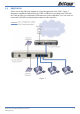
1.3 Application Please refer to the following diagram for a typical application of the V200. Figure 1 illustrates a simplified connection for the V200. In addition to providing basic VoIP calls, the V200 provides you with normal VoIP and router/switch capabilities, so it can work as a router and a VoIP ATA (analog telephone adapter) at the same time.
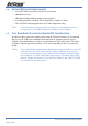
1.4 System Minimum Requirements • A valid SIP VoIP account from a VoIP Service Provider • A Broadband service • A Broadband Modem/Router (bridge-mode capable*) • An Analog telephone with RJ11 line cord (Desktop, Cordless or Dect.) • A PC with Web browsing application (for V200 configuration only) *Note: 1.5 In some cases, you may need to configure your broadband router in bridge-mode. The V200 will perform routing on your network.
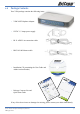
1.6 Package Contents Your V200 package contains the following items: • V200 VoIP Telephone Adaptor • 12VDC 1.5 Amps power supply • RJ-11 ADSL Line connection cable • RJ45 10/100 Ethernet cable • Installation CD (containing the User Guide and Adobe Acrobat Reader) • Package Contents List and Quick Start Guide If any of the above items are damaged or missing, please contact your dealer immediately.
1.
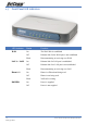
1.8 1.9 Back Panel and Wiring Label Description Reset Press button to restore the configuration to its factory state. WAN Connect to your ADSL modem LAN port with an RJ45 connector cable. Phone 1 ~ 2 Connect to one or two phones with an RJ11 connector cable. LAN Connect to your PCs (Ethernet ports) or a hub/switch with RJ45 connector cables. Power Connect to the power adapter and then plug the power adapter into the wall outlet.
Chapter 2 Quick Start 2.1 Before you begin You will need to collect your VoIP account details before you start to configure your V200. Details should include your SIP username/ VoIP number, your SIP account authentication ID and its password, SIP proxy server IP/URL, your VoIP network preferred codec and whether you need use STUN. When you open a VoIP account, your VoIP provider should provide you with this information.
2.2 Typical Network Connections for V200 The Quick Start section will show you how to connect the V200 to your network. A typical ADSL and cable broadband network are illustrated here. ADSL Broadband In general, a residential ADSL router runs PPPoE client and DHCP server for your PCs to share Internet access. In this case, you can just simply connect the V200 to your ADSL router as shown in Figure 2. Your PCs can connect to any LAN port in either the ADSL router or the V200.
Cable Broadband Figure 3 illustrates the V200 installation for cable broadband network.
2.3 Installation 2.3.1 Cable Connections • The Phone ports of the V200 are connected to a normal analog phone using a RJ11 cable. • The WAN port of the V200 is connected to your ADSL/Cable modem using a RJ45 cable. • A LAN port of the V200 is connected to your PC using a RJ45 cable. 2.3.2 Power on your V200 and PC Make sure all cables are connected properly, and then power on the V200. It will take approximately 1 to 2 minutes for the V200 to boot up.
Windows 2000 PCs First, check for the IP protocol and, if necessary, install it: 1. In the Windows task bar, click the Start button, point to Settings, and then click Control Panel. 2. Double-click the Network and Dial-up Connections icon. 3. In the Network and Dial-up Connections window, right-click the Local Area Connection icon, and then select Properties. 4. In the Local Area Connection Properties dialog box, select Internet Protocol (TCP/IP), and then click Properties 5.
Windows 95, 98 PCs First, check for the IP protocol and, if necessary, install it: 1. In the Windows task bar, click the Start button, point to Settings, and then click Control Panel. 2. Double-click the Network icon. 3. The Network dialog box displays with a list of currently installed network components. If the list includes TCP/IP, and then the protocol has already been enabled. Skip to step 9. 4.
2.3.4 Configure the V200 via Web browser This section describes how to logon and configure the V200 via a Web browser from your PC, which should be directly connected to the V200 via its LAN port. A. Logon to your V200 Open your Web browser (IE or Netscape) and type 192.168.30.1 in its address bar. You will see the login window. A unique default user account is assigned with user name admin and password admin. After you have logged in to the V200, you will be presented with the V200 Status page.
B. Select V200 WAN port type Click on WAN Setup menu item from the menu bar on the left hand side to bring up the WAN Setup window: By default, the WAN port is setup to operate in DHCP mode. This will work with a typical ADSL or cable broadband network as shown in Figures 2 & 3. The following screen shot is an example of the V200 in DHCP mode. If you are using a cable broadband service, you can simply use the V200 WAN port default setting as DHCP.
C. Configure V200 SIP On the V200 Configuration page, click the SIP button will bring a SIP configuration page. The following screen shows you an example of SIP configuration of the V200 which will allow the V200 to use “630801” and “683752” as its VoIP phone number and authentication ID to register on “fwd.pulver.com” SIP server. It will also show the use of STUN for traversing your router’s NAT/Firewall. Type in your SIP account information provided by your VoIP service provider in this page.
*Note: You must configure Account 1 and Account 2 on the above page before you can use the internal call feature. That means both Account 1 and Account 2 need to have a VoIP account information entered. In terms of the internal call, there is an alias “**” for Account 1 and Account 2. To make internal calls, just simply dial “**” and the other phone will ring.
D. Save your settings and Reboot the V200 Save your setting by clicking on the Save button under the System section After you save the settings, click the Reboot button to reboot the V200. You have completed the basic configuration of your V200. You have now completed the basic installation and configuration of your new NetComm V200. At this point you will be able to make VoIP calls to and from your V200 connection.
Appendix A: Cable Information This cable information is provided for your reference only. Please ensure you only connect the appropriate cable into the correct socket on either this product or your computer. If you are unsure about which cable to use or which socket to connect it to, please refer to the hardware installation section in this manual. If you are still not sure about cable connections, please contact a professional computer technician or NetComm for further advice.
Straight and crossover cable configuration There are two types of the wiring: Straight-Through Cables and Crossover Cables. Category 5 UTP/ STP cable has eight wires inside the sheath. The wires form four pairs. Straight-Through Cables has same pinouts at both ends while Crossover Cables has a different pin arrangement at each end. In a straight-through cable, wires 1,2,3,4,5,6,7 and 8 at one end of the cable are still wires 1~8 at the other end.
Appendix B: Glossary 100BaseT: A 100 Mbps Ethernet standard that uses twisted-pair wiring. 10BaseT: A 10 Mbps Ethernet standard that uses twisted-pair wiring. Arp: Address Resolution Protocol Address: The symbol (usually numeric) identifying an interface attached to a network. ASCII: American Standard Code for Information Interchange. Bandwidth: The range of frequencies of a transmission channel. The wider the range the higher the data rate that can be sent.
DSP: Digital Signal Processor. The microprocessor that handles line signaling in a modem. DTE: Data Terminal Equipment. Equipment that transmits or receives data in the form of digital signals. Dynamic detection: A process of a automatic detection of a new device added or removed from the PC. Ethernet address: Another name for MAC address. Ethernet: A standard protocol (IEEE 802.3) for a 10-Mb/s baseband local area network (PAT) bus that supports high-speed communication among systems.
ISP: Internet Service Provider. An organization that provides access to the Internet. Kbps: Literally it means Kilobits per second, but usually it is taken to mean 1,024 bits per second. LAN: Local Area Network. A LAN is a data communications system that lies within a limited spatial area, has a specific user group, and has a specific topology. LED: Light Emitting Diode. A light or status indicator. MAC address: Media Access Control address.
PPPoE: Point-to-Point Protocol over Ethernet. A method for establishing sessions and encapsulating PPP packets over an Ethernet, specified by RFC 2516. PPTP: Point-to-Point Tunneling Protocol. An extension of Point-to-Point Protocol used to create virtual private networks between PCs. Protocol: A set of rules that govern the transmission of data between interconnected devices to maintain or improve communication.
STUN: Simple Traversal of UDP (User Datagram Protocol) through NAT (Network Address Translation). Subnet address: The subnet portion of an IP address. Subnet mask: A number that identifies the subnet portion of a network address so that IP addresses can be shared on a local area network. Subnet: An independent network segment, that is, it has the same network address, but its subnet address is different.
Appendix C: Registration and Warranty Information All NetComm Limited (“NetComm”) products have a standard 12 month warranty from date of purchase against defects in manufacturing and that the products will operate in accordance with the specifications outlined in the User Guide. However some products have an extended warranty option (please refer to your packaging).
Product Warranty The warranty is granted on the following conditions: 1. This warranty extends to the original purchaser (you) and is not transferable; 2. This warranty shall not apply to software programs, batteries, power supplies, cables or other accessories supplied in or with the product; 3. The customer complies with all of the terms of any relevant agreement with NetComm and any other reasonable requirements of NetComm including producing such evidence of purchase as NetComm may require; 4.