
User's Manual
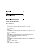
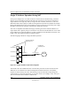

Table Of Contents
- Reference Manual for the NETGEAR ProSafe VPN Client
- Contents
- Chapter 1 About This Manual
- Chapter 2 Introduction
- Chapter 3 Installation
- Chapter 4 Configuring L2TP Connections
- Chapter 5 Using the Security Policy Editor
- What is the Security Policy Editor?
- Basic Steps to Configure a Security Policy
- How to Secure All Connections
- How to Configure Global Policy Settings
- How to Configure Other Connections
- How to Add and Configure a Connection
- How to Enter a Preshared Key
- How to Configure a Gateway
- Configure My Identity
- Configure Security Policy Connection Options
- Configure Authentication (Phase 1)
- Configure Key Exchange (Phase 2)
- Edit a Distinguished Name
- Configure and Manage Connections
- Manage Proposals
- Manage Redundant Gateways
- Manage the Security Policy
- Chapter 6 Using the Certificate Manager
- What is the Certificate Manager?
- Obtain Certificates
- With Online (SCEP) Enrollment
- CAs that Support SCEP
- Retrieve a CA Certificate Online
- Configure a CA Certificate
- Use an HTTP Proxy Server for Online Certificate Requests and CRL Updates
- Import a CA Certificate
- Select a CSP
- Request a Personal Certificate
- Define How Often to Check for and Retrieve New Personal Certificates
- Retrieve a Personal Certificate Manually
- Manage Certificate Requests
- With Manual (File-Based) Enrollment
- Obtain Certificates Through Internet Explorer
- With Online (SCEP) Enrollment
- Manage Certificates
- Manage Certificate Revocation Lists (CRLs)
- Manage the Trust Policy
- Chapter 7 Using Sessions
- Chapter 8 Distributing Customized Profiles
- Chapter 9 Troubleshooting
- Appendix A Networks, Routing, and Firewall Basics
- Appendix B Virtual Private Networking
- Appendix C NETGEAR ProSafe VPN Client to NETGEAR FVS318 or FVM318 VPN Routers
- Appendix D NETGEAR VPN Client to NETGEAR FVL328 or FWAG114 VPN Router
- Glossary
- Index

Reference Manual for the NETGEAR ProSafe VPN Client
A-4 Networks, Routing, and Firewall Basics
202-10015-01
This addressing structure allows IP addresses to uniquely identify each physical network and each
node on each physical network.
For each unique value of the network portion of the address, the base address of the range (host
address of all zeros) is known as the network address and is not usually assigned to a host. Also,
the top address of the range (host address of all ones) is not assigned, but is used as the broadcast
address for simultaneously sending a packet to all hosts with the same network address.
Netmask
In each of the address classes previously described, the size of the two parts (network address and
host address) is implied by the class. This partitioning scheme can also be expressed by a netmask
associated with the IP address. A netmask is a 32-bit quantity that, when logically combined (using
an AND operator) with an IP address, yields the network address. For instance, the netmasks for
Class A, B, and C addresses are 255.0.0.0, 255.255.0.0, and 255.255.255.0, respectively.
For example, the address 192.168.170.237 is a Class C IP address whose network portion is the
upper 24 bits. When combined (using an AND operator) with the Class C netmask, as shown here,
only the network portion of the address remains:
11000000 10101000 10101010 11101101 (192.168.170.237)
combined with:
11111111 11111111 11111111 00000000 (255.255.255.0)
Equals:
11000000 10101000 10101010 00000000 (192.168.170.0)
As a shorter alternative to dotted-decimal notation, the netmask may also be expressed in terms of
the number of ones from the left. This number is appended to the IP address, following a backward
slash (/), as “/n.” In the example, the address could be written as 192.168.170.237/24, indicating
that the netmask is 24 ones followed by 8 zeros.
Subnet Addressing
By looking at the addressing structures, you can see that even with a Class C address, there are a
large number of hosts per network. Such a structure is an inefficient use of addresses if each end of
a routed link requires a different network number. It is unlikely that the smaller office LANs would
have that many devices. You can resolve this problem by using a technique known as subnet
addressing.