Wireless-N ADSL2+ Modem Router DGN2000 Setup Manual NETGEAR, Inc. 4500 Great America Parkway Santa Clara, CA 95054 USA April 2008 208-10255-01 v1.
©2008 by NETGEAR, Inc. All rights reserved. Trademarks NETGEAR and the NETGEAR logo are trademarks of NETGEAR, Inc. Microsoft, Windows, and Windows NT are registered trademarks of Microsoft Corporation. Other brand and product names are registered trademarks or trademarks of their respective holders.
Contents Wireless-N ADSL2+ Modem Router DGN2000 Setup Manual Getting to Know Your Wireless Router ................................................................................. 1 Unpacking Your New Router ............................................................................................. 1 Hardware Features ............................................................................................................ 2 Front Panel ..................................................................
Troubleshooting .................................................................................................................... 29 Basic Functioning ............................................................................................................ 29 Power LED Not On .................................................................................................... 30 Power LED is Red .....................................................................................................
Getting to Know Your Wireless Router Congratulations on your purchase of a NETGEAR® high-speed wireless router, the DGN2000 Wireless-N ADSL2+ Modem Router. Before you begin installing your router, check the package contents (see “Unpacking Your New Router” on page 1). Become familiar with the front and back panels of your router—especially the LEDs—and the important information on the router label (see “Hardware Features” on page 2).
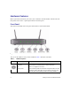
Hardware Features Before you install and connect your router, take a moment to become familiar with the front and back panels of the router—especially the LEDs on the front panel. Front Panel The wireless-N modem router front panel shown below contains status LEDs. Figure 1 You can use the LEDs to verify various conditions. Table 1 describes each LED. Table 1. LED Descriptions Label LED Activity Description Power Solid Green Power is supplied to the router.
Table 1. LED Descriptions (continued) Label LED Activity Description LAN Port 1 Solid Green The Local port has detected a link with a 100 Mbps device. Blinking Green Data is being transmitted or received at 100 Mbps. Solid Amber The Local port has detected a link with a 10 Mbps device. Blinking Amber Data is being transmitted or received at 10 Mbps. Off No link is detected on this port.
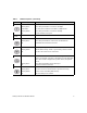
Back Panel The back panel of the wireless-N modem router contains port connections. 1 2 3 4 Figure 2 Viewed from left to right, the rear panel contains the following elements: 1. RJ-11 ADSL port for connecting the wireless-N modem router to an ADSL line 2. Four Local Ethernet RJ-45 LAN ports for connecting the wireless-N modem router to the local computers 3. AC power adapter input 4.
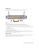
Figure 3 Positioning Your Wireless Router The wireless-N modem router lets you access your network from virtually anywhere within the operating range of your wireless network. However, the operating distance or range of your wireless connection can vary significantly depending on the physical placement of your router. For example, the thickness and number of walls the wireless signal must pass through may limit the range.
Installing Your Wireless-N Modem Router To help you set up your router and get on the Internet quickly, the Resource CD contains a Smart Wizard™. The Smart Wizard walks you through the steps required to connect your router, microfilters, and PC(s); configure your wireless settings; and enable wireless security for your network.
Updating Your Router Firmware NETGEAR is always improving the operability and features of its routers. To make it easy for you to receive feature innovations and software updates, NETGEAR has included an automatic software update utility on the Resource CD. This utility will periodically check the NETGEAR support site to see if a newer version of software is available for your router. If a new version is found, you will be prompted to update your router with the new firmware.
8 Getting to Know Your Wireless Router
Installing Your Router Using the Smart Wizard To use the Smart Wizard, you must be using a PC with Windows Vista, or Windows 2000, or Windows XP with Service Pack 2. The Smart Wizard setup procedure should take about 15 minutes to complete. Before using the Smart Wizard to set up your wireless-N modem router, ensure that: • You have an ADSL Internet service connection through an Internet Service Provider (ISP). • You have the configuration information provided by your ISP.
you can always access the router’s user interface later to select a security option (see “Accessing Your Router After Installation” on page 10). To ensure optimum performance of your high-speed wireless router, the wireless adapter card for each computer in your network should support the same technology as your router (see the online Reference Manual for more information).
Installing Your Router Manually (Advanced, Mac, and Linux Users) Before installing and connecting your router manually, review the list below and make sure that you have all of the necessary information. • Internet ADSL service connection through an Internet Service Provider (ISP). • The configuration information your ISP gave you.
Understanding ADSL Microfilters ADSL technology uses the same wires as your telephone service. However, ADSL adds signals to the telephone lines which create noise in the telephone service. You must use ADSL microfilters to filter out these signals before they reach your telephone. If you purchased the wireless-N modem router in a country where a microfilter is not included, you must acquire one.
Connecting Your Wireless-N Modem Router Before you install your wireless-N modem router, make sure that the Internet Protocol (TCP/IP) Property settings on your computer are set to “automatically obtain an IP address” using DHCP and “Obtain DNS server address automatically.” You can check these settings by looking at the TCP/IP Properties of your Internal Network Connections, which are accessible through the Control Panel of your computer.
• Two-Line Filter Example. Insert the two-line filter into the phone outlet and connect the phone to the phone line connector (A), as shown in Figure 7. A Figure 7 To use a one-line filter with a separate splitter, insert the splitter into the phone outlet, connect the one-line filter to the splitter, and connect the phone to the filter. 2. Connect the wireless-N modem router to the ADSL filter.
. C B Figure 8 Improperly connecting a filter to your wireless-N modem router will block your ADSL connection. 3. Connect the Ethernet cable (D) from a wireless-N modem router LAN port to the Ethernet adapter in your computer, as shown in Figure 9. 4. Connect the power adapter to the wireless-N modem router and plug it in to a power outlet.
D Figure 9 5. Connect any additional wired PCs to your router by inserting an Ethernet cable from a PC into one of the three remaining LAN ports. Verifying Your Connection Verify that your router is connected correctly by checking the wireless-N modem router status lights. • The power light is lit after turning on the wireless-N modem router. • The DSL light is lit, indicating an ADSL connection. • The wireless light is lit after turning on the wireless-N modem router.
Setting Up Your Router for Internet Access When configuring your wireless router manually, you must log in to your wireless-N modem router to set it up initially and to make any changes to your wireless router’s settings later. The factory default state is reset when you use the Restore Factory Settings button. See “Restoring the Default Configuration and Password” on page 36 for more information. To access the router: 1. Type http://192.168.0.1 in the address field of your browser, and then click Enter.
2. When prompted, enter admin for the router User Name and password for the router Password, both in lowercase letters. (For security reasons, the router has its own user name and password.) The router user name and password are not the same as any user name or password you may use to log in to your Internet connection. The Main menu will display. 3. From the menu options in the left navigation pane, click Setup Wizard. The Setup Wizard screen will display. Figure 12 4.
If you do not connect successfully: • Review your settings and make sure that you have selected the correct options and typed everything correctly. • Contact your ISP to verify that you have the correct configuration information. • Read “Troubleshooting” on page 29. If problems persist, register your NETGEAR product and contact NETGEAR Technical Support.
20 Installing Your Router Manually (Advanced, Mac, and Linux Users)
Configuring Your Wireless Network After installing your router, you must log into the router to complete your wireless setup. The wireless network settings of the router must match the wireless network settings of any wireless devices that connect wirelessly to the router (such as wireless adapter cards and wireless computers). For a wireless connection, the router and each wireless computer must use the same SSID, also called the wireless network name, and the same wireless security.
Setting Your SSID and Wireless Security Manually To specify the wireless settings, you must know the following: • SSID. The default SSID for the router is NETGEAR. • The wireless mode (802.11g/b, or 802.11n) that each wireless adapter supports. • Wireless security option. NETGEAR strongly recommends that you use wireless security. To successfully implement wireless security, check each wireless adapter to determine which wireless security option it supports. To set up basic wireless connectivity: 1.
3. Check that the security settings on each wireless device match the security settings of the router. For example, if you selected a security option requiring a passphrase, then the same passphrase must be used for each wireless computer. 4. Check that each wireless computer has a wireless link and is able to obtain an IP address by DHCP from the router. For a Windows PC, go to the Control Panel and select Network Connections.
These instructions assume that you are configuring WPS on the router for the first time and connecting a WPS-capable device. To set up basic wireless connectivity: 1. Log in to the wireless-N modem router at its default LAN address of http://Default IP Address Variable with its default user name of admin and default password of password, or using whatever LAN address and password you have set up. You can also enter either of these addresses to connect to your wireless router: http://www.routerlogin.
: Figure 14 • Entering a PIN. If you want to use the PIN method, select the PIN radio box. A screen similar to the one shown below displays. – Go to your wireless client and, from the client’s WPS utility, obtain the wireless client’s security PIN, or follow the client’s WPS utility instructions to generate a security PIN. – Then, enter this PIN in the Enter Client’s PIN field provided on the router and click Next. You have 4 minutes to enable WPS on the router using this method.
To access the Internet from any computer connected to your wireless-N modem router, launch a browser such as Microsoft Internet Explorer or Netscape Navigator. You should see the wireless-N modem router’s Internet LED blink, indicating communication to the ISP. If you are planning a mixed network of WPS capable devices and non-WPS capable devices, NETGEAR suggests that you set up your wireless network and security settings manually first, and use WPS only for adding additional WPS capable devices.
6. Click Apply to save your changes. If you are configuring the Product Family from a wireless computer and you change the Product Family’s SSID, channel, or security settings, you will lose your wireless connection when you click Apply. You must then change the wireless settings of your computer to match the Product Family’s new settings. 7. Configure and test your computers for wireless connectivity.
28 Configuring Your Wireless Network
Troubleshooting This chapter gives information about troubleshooting your wireless-N modem router. After each problem description, instructions are provided to help you diagnose and solve the problem. For the common problems listed, go to the section indicated. • Is the router on? Go to “Basic Functioning” on page 29. • Have I connected the router correctly? Go to “Troubleshooting the Web Configuration Interface” on page 31. • I cannot access the router’s configuration with my browser.
If a port’s LED is lit, a link has been established to the connected device. If a LAN port is connected to a 100 Mbps device, verify that the port’s LED is green. If the port is 10 Mbps, the LED will be amber. If any of these conditions does not occur, refer to the appropriate following section.
• Be sure you are using the correct cable: when connecting the ADSL port, use the cable that was supplied with the wireless-N modem router. If the Internet LED is still off, this may mean that there is no ADSL service or the cable connected to the ADSL port is bad.
Troubleshooting the ISP Connection If your router is unable to access the Internet, you should check the ADSL connection, then the Internet TCP/IP connection. ADSL link If your router is unable to access the Internet, you should first determine whether you have an ADSL link with the service provider. The state of this connection is indicated with the Internet LED. Internet LED Green or Blinking Green If your ADSL Internet LED is green or blinking green, then you have a good ADSL connection.
• Verify that you are connected to the correct telephone line. If you have more than one phone line, be sure that you are connected to the line with the ADSL service. It may be necessary to use a swapper if you ADSL signal is on pins 1 and 4 of the RJ-11 jack. The Wireless-N Modem Router uses pins 2 and 3.
Troubleshooting PPPoE or PPPoA The PPPoE or PPPoA connection can be debugged as follows: 1. Access the Main Menu of the router at http://192.168.0.1. 2. Under the Maintenance heading, select the Router Status link. 3. Click the Connection Status button. 4. If all of the steps indicate “OK” then your PPPoE or PPPoA connection is up and working. 5. If any of the steps indicates “Failed”, you can attempt to reconnect by clicking “Connect”.
Troubleshooting a TCP/IP Network Using the Ping Utility Most TCP/IP terminal devices and routers contain a ping utility that sends an echo request packet to the designated device. The device then responds with an echo reply. Troubleshooting a TCP/IP network is made easy by using the ping utility in your computer. Testing the LAN Path to Your Router You can ping the router from your computer to verify that the LAN path to your router is set up correctly.
– Verify that the IP address for your router and your workstation are correct and that the addresses are on the same subnet. Testing the Path from Your Computer to a Remote Device After verifying that the LAN path works correctly, test the path from your PC to a remote device. From the Windows run menu, type: PING -n 10 where is the IP address of a remote device such as your ISP’s DNS server. If the path is functioning correctly, replies as in the previous section are displayed.
2. Release the Default Reset button and wait for the router to reboot.The Power LED will blink red three times and then will turn green when the default configuration settings have been restored.
38 Troubleshooting
Technical Specifications This appendix provides technical specifications for the wireless-N modem router. General Specifications Network Protocol and Standards Compatibility Data and Routing Protocols: TCP/IP, RIP-1, RIP-2, DHCP, PPPoE or PPPoA, RFC 1483 Bridged or Routed Ethernet, and RFC 1577 Classical IP over ATM Power Adapter North America: 120V, 60 Hz, input UK, Australia: 240V, 50 Hz, input Europe: 230V, 50 Hz, input All regions (output): 12 V AC @ 1.0A output Physical Dimensions: 7.
Interface Specifications LAN: 10BASE-T or 100BASE-Tx, RJ-45 WAN: ADSL, Dual RJ-11, pins 2 and 3 T1.413, G.DMT, G.Lite Default Configuration You can use the reset button located on the front of your device to reset all settings to their factory defaults. This is called a hard reset. To perform a hard reset, push and hold the reset button for three seconds. Your device will return to the factory configuration settings shown in the table below.
Feature Default Behavior Time Zone Adjusted for Daylight Saving Time Disabled SNMP Disabled Firewall Inbound (communications coming in from Disabled (except traffic on port 80, the http port) the Internet) Outbound (communications going out to the Internet) Enabled (all) Source MAC filtering Disabled Wireless Wireless Communication Enabled SSID Name NETGEAR Security Disabled Broadcast SSID Enabled Transmission Speed Autoa Country/Region United States (in North America; otherwise, varies
42 Technical Specifications
Related Documents This appendix provides links to reference documents you can use to gain a more complete understanding of the technologies used in your NETGEAR product. Document Link ITCP/IP Networking Basics http://documentation.netgear.com/reference/enu/tcpip/index.htm Wireless Networking Basics http://documentation.netgear.com/reference/enu/wireless/index.htm Preparing Your Network http://documentation.netgear.com/reference/enu/wsdhcp/index.
44 Related Documents
Registration and Certifications Product Registration, Support, and Documentation Register your product at http://www.NETGEAR.com/register. You must register before you can use our telephone support service. Product updates and Web support are always available by going to: http://kbserver.netgear.com/. Setup documentation is available on the CD, on the support website, and on the documentation website.
46