
User's Manual


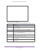


Table Of Contents
- AC1900, N900, and N450 WiFi Cable Data Gateways
- Contents
- 1. Hardware Overview
- 2. Connect and Get Started
- 3. Configure Parental Controls and Basic WiFi Settings
- 4. Manage Internet, WAN, and LAN Settings and Use the WPS Wizard
- 5. Manage the Firewall and Secure Your Network
- 6. Manage and Monitor Your Network
- View the Status and Statistics of the WiFi Cable Data Gateway
- View the WiFi Cable Data Gateway Cable Initialization
- View the Network Map
- View WiFi Channels in Your Environment
- View WiFi Access Points in Your Environment
- View and Manage the Log
- Manage the WiFi Cable Gateway Settings
- Return the WiFi Cable Data Gateway to Its Factory Default Settings
- Reboot the Cable Data Gateway
- 7. Share USB Drives Attached to the Cable Data Gateway
- USB Drive Requirements
- Access a USB Drive on the Network
- Back Up Windows Computers with ReadySHARE Vault
- Specify the Method for Accessing the USB Drive
- View Network Folders on a USB Drive
- Add a Network Folder on a USB Drive
- Change a Network Folder, Including Read and Write Access, on a USB Drive
- Safely Remove a USB Drive
- Enable the Media Server
- 8. Configure Advanced Features
- Manage Advanced WiFi Settings
- Port Forwarding and Port Triggering Concepts
- Set Up Port Forwarding to Local Computers
- Set Up and Manage Port Triggering
- Set Up and Manage IP Address Filtering
- Set Up and Manage MAC Address Filtering
- Configure Dynamic DNS
- Manage the Cable Data Gateway Remotely
- Manage Universal Plug and Play
- Manage the Network Address Translation
- Manage the Ethernet Ports of the LAN Switch
- Manage Network Time Protocol
- 9. Diagnostics and Troubleshooting
- A. Factory Default Settings and Specifications

Configure Advanced Features
130
AC1900, N900, and N450 WiFi Cable Data Gateways
The following table describes the fields on the Port Triggering - Services screen.
Field Description
Service
Service Name Enter a descriptive name.
Service User From the menu, select if any internal IP address can connect to the service or
application or only a single IP address can connect. If you select Single address
from the menu, enter the IP address.
Service Type From the menu, select the correct type of protocol for the service or application
(TCP or UDP).
Triggering Port Enter the internal starting port number for the service or application. This number
represents the outbound traf
fic port that must cause the inbound ports (see
Inbound Connection later in this table) to be opened.
T
riggering Ending Port If the service or application uses a single triggering port, enter the same port
number that you enter in the T
riggering Port
field.
If the service or application uses a range of triggering ports, enter the ending port
number of the range.
Inbound Connection
Starting Port Enter the starting port number for the inbound connection. This number represents
the inbound traf
fic port that is triggered open by the triggering port.
Ending Port If the service or application uses a single ending port for the inbound connection,
enter the same port number that you enter in the
Starting Port field.
If the service or application uses a range of ports for the inbound connection, enter
the ending port number of the range.
9. Click the Apply button.
The service or application is added to the Port Triggering Portmap Table. The Enable
check box is selected automatically.
10. In the Port T
riggering section, select how the cable data gateway applies port triggering:
• Per Schedule. Port triggering is enabled according the schedule that you must select
from the menu.
For more information, see Schedule When Features Are Active on page 68.
• Always. Port triggering is always enabled.
Note: By default, the Never radio button is selected and port triggering is
disabled, even if you specified services and applications in the table.
11. Click the Apply button.
Your settings are saved.