User Manual for the NETGEAR 7200 Series Layer 2 Managed Switch Software NETGEAR, Inc.
© 2003 by NETGEAR, Inc., 202-10010-01 , November 2003. FullManual All rights reserved. Technical Support Please register to obtain technical support. Please retain your proof of purchase and warranty information. To register your product, get product support or obtain product information and product documentation, go to http://www.netgear.com. If you do not have access to the World Wide Web, you may register your product by filling out the registration card and mailing it to NETGEAR customer service.
Canadian Department of Communications Compliance Statement This Class B Digital apparatus (GSM7224 Layer 2 Managed Switch) meets all the requirements of the Canadian Interference Causing Equipment Regulations. Cet appareil numerique del la classe B respect les exigences du Regalement sur le material broilleur du Canada. This device comples with Class B limits of Industry of Canada. Operation is subject to the following two conditions: 1. This device may not cause harmful interference. 2.
iv 202-10010-01
Contents Chapter 1 About This Guide Audience .........................................................................................................................1-1 Why the Document was Created ....................................................................................1-1 How to Use This Document ............................................................................................1-1 Typographical Conventions .............................................................................
System-Wide Popup Menus .....................................................................................5-4 Port-Specific Popup Menus ......................................................................................5-4 Chapter 6 Quick Startup Quick Starting the Switch ................................................................................................6-1 System Info and System Setup ......................................................................................
Management Commands .............................................................................................7-13 show network .........................................................................................................7-13 config network macaddr .........................................................................................7-13 config network mactype .........................................................................................7-14 config network parms ................
config telnet mode ..................................................................................................7-22 config telnet timeout ...............................................................................................7-22 show forwardingdb agetime ...................................................................................7-23 config forwardingdb agetime ..................................................................................7-23 Device Configuration Commands .........
config vlan port ingressfilter ...................................................................................7-33 show protocol .........................................................................................................7-33 config protocol create .............................................................................................7-33 config protocol delete .............................................................................................
config macfilter create ............................................................................................7-43 config macfilter remove ..........................................................................................7-44 config macfilter addsrc ...........................................................................................7-44 config macfilter delsrc ............................................................................................7-44 config macfilter adddest ......
show spanningtree mst port summary ...................................................................7-55 show spanningtree mst port detailed .....................................................................7-55 show spanningtree vlan .........................................................................................7-55 User Account Management Commands .......................................................................7-56 show users ..........................................................
config dot1x port initialize .......................................................................................7-65 config dot1x port reauthenticate .............................................................................7-65 config dot1x port controldir .....................................................................................7-66 config dot1x port controlmode ................................................................................7-66 config dot1x port quietperiod ............
transfer upload filename .........................................................................................7-76 transfer upload datatype ........................................................................................7-76 transfer upload start ...............................................................................................7-76 transfer download mode .........................................................................................7-76 transfer download serverip .........
Appendix B Glossary Numeric ........................................................................................................................10-1 A ...................................................................................................................................10-2 B ...................................................................................................................................10-2 C .................................................................................
Chapter 1 About This Guide Thank you for purchasing the NETGEAR™ GSM7224 L2 Switch. Audience This reference manual assumes that the reader has basic-to-intermediate computer and Internet skills. However, basic computer network, Internet, and wireless technology tutorial information is provided in the Appendices. This document describes configuration commands for the GSM7224 Layer 2 Managed Switch software. The commands can be accessed from the CLI, telnet, and Web interfaces.
User Manual for the NETGEAR 7200 Series Layer 2 Managed Switch Software Note: Refer to the release notes for the GSM7224 Layer 2 Managed Switch Software application level code. The release notes detail the platform specific functionality of the Switching, SNMP, Config, and Management packages. Typographical Conventions This guide uses the following typographical conventions: Table 1. Typographical conventions italics Emphasis. bold times roman User input.
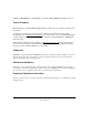
User Manual for the NETGEAR 7200 Series Layer 2 Managed Switch Software Features of the HTML Version of this Manual The HTML version of this manual includes these features. 2 1 3 Figure Preface -2: HTML version of this manual 1. Left pane. Use the left pane to view the Contents, Index, Search, and Favorites tabs. To view the HTML version of the manual, you must have a version 4 or later browser with JavaScript enabled. 2. Toolbar buttons.
User Manual for the NETGEAR 7200 Series Layer 2 Managed Switch Software How to Print this Manual To print this manual you man choose one of the following several options, according to your needs. • Printing a “How To” Sequence of Steps in the HTML View. Use the Print button on the upper right of the toolbar to print the currently displayed topic.
Chapter 2 Switch Management Overview This chapter gives an overview of switch management, including the methods you can use to manage your NETGEAR GSM7224 Layer 2 Managed Switch. • Management Access Overview • SNMP Access • Protocols Scope The GSM7224 Layer 2 Managed Switch software has two purposes: • Assists attached hardware in switching frames, based on Layer 2 information contained in the frames. • Provides a complete switch management portfolio for the network administrator.
User Manual for the NETGEAR 7200 Series Layer 2 Managed Switch Software • Simple Network Protocol Management (SNMP) Each management method enables the network administrator to configure, manage, and control the GSM7224 locally or remotely using in-band or out-of-band mechanisms. Management is standards-based, with configuration parameters and a private MIB providing control for functions not completely specified in the MIBs. Table 2-1.
User Manual for the NETGEAR 7200 Series Layer 2 Managed Switch Software Chapter 3 Command Line Interface Syntax The Command Line Interface (CLI) syntax, conventions and terminology are described in this section. Each CLI command is illustrated using the structure outlined below. Format Commands are followed by values, parameters or both. Example 1 config network parms [gateway] • • • config network parms is the command name.
User Manual for the NETGEAR 7200 Series Layer 2 Managed Switch Software Command The text in bold, non-italic font must be typed exactly as shown. Parameters Parameters are order dependent. The text in bold italics should be replaced with a name or number. To use spaces as part of a name parameter, enclose it in double quotes like this: "System Name with Spaces". Parameters may be mandatory values, optional values, choices or a combination. – .
User Manual for the NETGEAR 7200 Series Layer 2 Managed Switch Software number 1. The field is composed of a valid slot number and a valid port number separated by a period (.). logical slot.port This parameter denotes a logical slot number and logical port number assigned. This is applicable in the case of a LAG. The operator can use the logical slot number and the logical port number to configure the LAG.
User Manual for the NETGEAR 7200 Series Layer 2 Managed Switch Software Annotations The CLI allows the user to type single-line annotations at the command prompt for use when writing test or configuration scripts and for better readability. The exclamation point (‘!’) character flags the beginning of a comment. The comment flag character can begin a word anywhere on the command line and all input following this character is ignored.
Chapter 4 Administration Console Telnet Interface The administration console is an internal, character-oriented, VT-100/ANSI menu-driven user interface for performing management activities. Using this method, you can view the administration console from a terminal, PC, Apple Macintosh, or UNIX workstation connected to the switch’s console port. Figure 4-1 shows an example of this management method.
User Manual for the NETGEAR 7200 Series Layer 2 Managed Switch Software Examples of terminal-emulation programs include: • HyperTerminal, which is included with Microsoft Windows operating systems • ZTerm for the Apple Macintosh • TIP for UNIX workstations This example describes how to set up the connection using HyperTerminal on a PC, but other systems follow similar steps. 1. Click the Windows Start button. Select Accessories and then Communications.
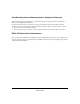
User Manual for the NETGEAR 7200 Series Layer 2 Managed Switch Software 4. When the following screen appears, make sure that the port setting are as follows: Baud Rate: Data Bits: Parity: Stop Bits: Flow Control: 9600 8 None 1 None Figure 4-4: Connection Settings 5. Click OK. The HyperTerminal window opens and you should be connected to the switch. If you do not get a welcome screen or a system menu, hit the return key.
User Manual for the NETGEAR 7200 Series Layer 2 Managed Switch Software 4-4 Administration Console Telnet Interface 202-10010-01
Chapter 5 Web-Based Management Interface Your NETGEAR GSM7224 Layer 2 Managed Switch provides a built-in browser interface that lets you configure and manage it remotely using a standard Web browser such as Microsoft Internet Explorer 5.0 or later or Netscape Navigator 6.0 or later. This interface also allows for system monitoring and management of the switch. The ‘help’ page covers many of the basic functions and features of the switch and it’s web interface.
User Manual for the NETGEAR 7200 Series Layer 2 Managed Switch Software • Device Management Introduction of the basic icons and management of the device • Interface Operations Describes Web browser requirements, and common commands • Product Overview Describes supported SNMP and Web management features • Summary of Features Feature List How to Log In to the GSM7224 The GSM7224 Layer 2 Managed Switch can be configured remotely from Microsoft Internet Explorer browser version 5.
User Manual for the NETGEAR 7200 Series Layer 2 Managed Switch Software 4. Type the default user name of admin and default of no password, or whatever password you have set up. Once you have entered your access point name, your Web browser should automatically find the GSM7224 L2 Switch and display the home page, as shown below.
User Manual for the NETGEAR 7200 Series Layer 2 Managed Switch Software System-Wide Popup Menus The GSM7224 L2 Switch also provides several popup menus. You can also access the main navigation menu by right clicking on the image of the switch and browsing to the menu you want to use. Port-Specific Popup Menus The GSM7224 L2 Switch also provides several popup menus for each port.
User Manual for the NETGEAR 7200 Series Layer 2 Managed Switch Software Chapter 6 Quick Startup The Command Line Interface Quick Startup chapter details procedures to quickly become acquainted with the GSM7224 Layer 2 Managed Switch software. This chapter contains the following Quick Startup examples: • “System Info and System Setup” on page 6-2 • “VLAN Configuration Example” on page 6-8 Quick Starting the Switch 1. Read the device Installation Guide for the connectivity procedure.
User Manual for the NETGEAR 7200 Series Layer 2 Managed Switch Software System Info and System Setup There are several categories of Quick Startup commands: • “Quick Startup Software Version Information” on page 6-2 • “Quick Startup Physical Port Data” on page 6-3 • “Quick Startup User Account Management” on page 6-3 • “Quick Startup IP Address” on page 6-4 • “Quick Startup Uploading from Switch to Out-of-Band PC (Only XMODEM)” on page 6-6 • “Quick Startup Downloading from Out-of-Band PC to Swit
User Manual for the NETGEAR 7200 Series Layer 2 Managed Switch Software Quick Startup Physical Port Data Table 6-2. Quick Startup Physical Port Data Command Details show port all Displays the Port Characteristics Slot.Port - slot number.port number Slot Options: 0 - the port is one of the physical ports 1 - a link aggregation group (LAG). The port number field in this case refers to the LAG group ID. 3 - a VLAN group. The port field starts with 1 as the first VLAN group created in the switch.
User Manual for the NETGEAR 7200 Series Layer 2 Managed Switch Software Table 6-3. Quick Startup User Account Management Command Details show loginsession Displays all of the login session information config users passwd Allows the user to set passwords or change passwords needed to log in. A prompt appears requesting the users old password. In the absence of an old password leave the area blank. The operator must press enter to execute the command.
User Manual for the NETGEAR 7200 Series Layer 2 Managed Switch Software Table 6-4. Quick Startup IP Address Command Details Default Gateway - The default Gateway for this interface Default value is 0.0.0.
User Manual for the NETGEAR 7200 Series Layer 2 Managed Switch Software Quick Startup Uploading from Switch to Out-of-Band PC (Only XMODEM) Table 6-5.
User Manual for the NETGEAR 7200 Series Layer 2 Managed Switch Software Quick Startup Downloading from TFTP Server Before starting a TFTP server download, the operator must complete the Quick Startup for the IP Address. Table 6-7. Quick Startup Downloading from TFTP Server Command Details transfer download mode TFTP Makes the download mode to be TFTP transfer download datatype Sets the download datatype to be an image or config file. The default is a code file.
User Manual for the NETGEAR 7200 Series Layer 2 Managed Switch Software VLAN Configuration Example This section provides configuration examples for VLAN configurations. LAN switches can segment networks into logically defined virtual workgroups.This logical segmentation is commonly referred as a virtual LAN (VLAN). This logical segmentation of devices provides better LAN administration, security, and management of broadcast activity over the network.
User Manual for the NETGEAR 7200 Series Layer 2 Managed Switch Software Table 6-9. Creating the VLANs VLAN Command create VLAN 4 config vlan create 4 config vlan participation include 4 0.5 config vlan participation include 4 0.
User Manual for the NETGEAR 7200 Series Layer 2 Managed Switch Software 6-10 Quick Startup 202-10010-01
User Manual for the NETGEAR 7200 Series Layer 2 Managed Switch Software Chapter 7 Switching Commands This chapter provides detailed explanation of the Switching commands. The commands are divided into five functional groups: • Show commands display switch settings, statistics, and other information. • Config commands configure features and options of the switch. For every config command there is a show command that displays the config setting.
User Manual for the NETGEAR 7200 Series Layer 2 Managed Switch Software Switch Description Machine Type Machine Model Serial Number FRU Number Part Number Maintenance Level Manufacturer Burnedin MAC Address Software Version Text used to identify the product name of this switch. Specifies the machine model as defined by the Vital Product Data. Specifies the machine model as defined by the Vital Product Data. The unique box serial number for this switch. The field replaceable unit number.
User Manual for the NETGEAR 7200 Series Layer 2 Managed Switch Software config syslocation This command sets the physical location of the switch. The range for the name is from 1 to 31 alphanumeric characters. Default Format Blank config syslocation config syscontact This command sets the organization responsible for the network. The range for the name is from 1 to 31 alphanumeric characters.
User Manual for the NETGEAR 7200 Series Layer 2 Managed Switch Software Slot.Port if Index Status The port which this address was learned. This object indicates the ifIndex of the interface table entry associated with this port. The status of this entry. The meanings of the values are: Static - The value of the corresponding instance was added by the system or a user and cannot be relearned. Learned - The value of the corresponding instance was learned, and is being used.
User Manual for the NETGEAR 7200 Series Layer 2 Managed Switch Software Octets Received - the total number of octets of data (including those in bad packets) received on the network (excluding framing bits but including FCS octets). This object can be used as a reasonable estimate of ethernet utilization. If greater precision is desired, the etherStatsPkts and etherStatsOctets objects should be sampled before and after a common interval.
User Manual for the NETGEAR 7200 Series Layer 2 Managed Switch Software Total - the total number of inbound packets that contained errors preventing them from being deliverable to a higher-layer protocol. Jabbers Received - the total number of packets received that were longer than 1518 octets (excluding framing bits, but including FCS octets), and had either a bad Frame Check Sequence (FCS) with an integral number of octets (FCS Error) or a bad FCS with a non-integral number of octets (Alignment Error).
User Manual for the NETGEAR 7200 Series Layer 2 Managed Switch Software CFI Discards - the number of frames discarded that have CFI bit set and the addresses in RIF are in non-canonical format. Upstream Threshold - the number of frames discarded due to lack of cell descriptors available for that packet's priority level. Packets Transmitted Octets Total Bytes - the total number of octets of data (including those in bad packets) received on the network (excluding framing bits but including FCS octets).
User Manual for the NETGEAR 7200 Series Layer 2 Managed Switch Software Total Errors - the sum of Single, Multiple, and Excessive Collisions. FCS Errors - the total number of packets transmitted that had a length (excluding framing bits, but including FCS octets) of between 64 and 1518 octets, inclusive, but had a bad Frame Check Sequence (FCS) with an integral number of octets Oversized - the total number of frames that exceeded the max permitted frame size.
User Manual for the NETGEAR 7200 Series Layer 2 Managed Switch Software STP BPDUs Transmitted - Spanning Tree Protocol Bridge Protocol Data Units sent STP BPDUs Received - Spanning Tree Protocol Bridge Protocol Data Units received RST BPDUs Transmitted - Rapid Spanning Tree Protocol Bridge Protocol Data Units sent RSTP BPDUs Received - Rapid Spanning Tree Protocol Bridge Protocol Data Units received MSTP BPDUs Transmitted - Multiple Spanning Tree Protocol Bridge Protocol Data Units sent MSTP BPDUs Received
User Manual for the NETGEAR 7200 Series Layer 2 Managed Switch Software show stats switch detailed This command displays detailed statistics for all CPU traffic. Format show stats switch detailed Total Packets Received (Octets) - the total number of octets of data received by the processor (excluding framing bits but including FCS octets). Packets Received Without Error - the total number of packets (including broadcast packets and multicast packets) received by the processor.
User Manual for the NETGEAR 7200 Series Layer 2 Managed Switch Software Most VLAN Entries Ever Used - the largest number of VLANs that have been active on this switch since the last reboot. Static VLAN Entries - the number of presently active VLAN entries on this switch that have been created statically. Dynamic VLAN Entries - the number of presently active VLAN entries on this switch that have been created by GVRP registration.
User Manual for the NETGEAR 7200 Series Layer 2 Managed Switch Software show eventlog This command displays the event log, which contains error messages from the system. The event log is not cleared on a system reset. Format File Line Task Id Code Time show eventlog The file in which the event originated. The line number of the event. The task ID of the event. The event code. The time this event occurred. Note: Event log information is retained across a switch reset.
User Manual for the NETGEAR 7200 Series Layer 2 Managed Switch Software Management Commands These commands manage the switch and show current management settings. show network This command displays network configuration settings that are vital for switch operation. Format IP Address Subnet Mask Default Gateway BurnedIn MAC Address Locally Administered MAC Address MAC Address Type Network Configuration Protocol Current Web Mode Java Mode show network The IP address of the interface.
User Manual for the NETGEAR 7200 Series Layer 2 Managed Switch Software • Bit 7 of byte 0 (called the I/G bit) indicates whether the destination address is an individual address (b'0') or a group address (b'1'). • The second character, of the twelve character macAddr, must be 2, 6, A or E. A locally administered address must have bit 6 On (b'1') and bit 7 Off (b'0').
User Manual for the NETGEAR 7200 Series Layer 2 Managed Switch Software Default Format enable config network webmode config network javamode This command specifies whether or not the switch should allow access to the Java applet in the header frame of the Web interface. When access is enabled, the Java applet can be viewed from the Web interface. When access is disabled, the user cannot view the Java applet.
User Manual for the NETGEAR 7200 Series Layer 2 Managed Switch Software config serial baudrate This command specifies the communication rate of the terminal interface. The supported rates are 1200, 2400, 4800, 9600, 19200, 38400, 57600, 115200. Default Format 9600 config serial baudrate config serial timeout This command specifies the maximum connect time (in minutes) without console activity. A value of 0 indicates that a console can be connected indefinitely. The time range is 0 to 160.
User Manual for the NETGEAR 7200 Series Layer 2 Managed Switch Software show snmpcommunity This command displays SNMP community information. Six communities are supported. You can add, change, or delete communities. The switch does not have to be reset for changes to take effect. The SNMP agent of the switch complies with SNMP Version 1 (for more about the SNMP specification, see the SNMP RFCs).
User Manual for the NETGEAR 7200 Series Layer 2 Managed Switch Software config snmpcommunity create This command adds (and names) a new SNMP community. A community name is a name associated with the switch and with a set of SNMP managers that manage it with a specified privileged level. The length of name can be up to 16 case-sensitive characters. Note: Community names in the SNMP community table must be unique.
User Manual for the NETGEAR 7200 Series Layer 2 Managed Switch Software config snmpcommunity mode This command activates or deactivates an SNMP community. If a community is enabled, an SNMP manager associated with this community manages the switch according to its access right. If the community is disabled, no SNMP requests using this community are accepted. In this case the SNMP manager associated with this community cannot manage the switch until the Status is changed back to Enable.
User Manual for the NETGEAR 7200 Series Layer 2 Managed Switch Software config snmptrap ipaddr This command assigns an IP address to a specified community name. The maximum length of name is 16 case-sensitive alphanumeric characters. Note: IP addresses in the SNMP trap receiver table must be unique. If you make multiple entries using the same IP address, the first entry is retained and processed. All duplicate entries are ignored.
User Manual for the NETGEAR 7200 Series Layer 2 Managed Switch Software config trapflags authentication This command enables or disables the Authentication Flag. Default Format enable config trapflags authentication config trapflags bcaststorm This command enables or disables the broadcast storm trap. When enabled, broadcast storm traps are sent only if the broadcast storm recovery mode setting associated with the port is enabled (see “config switchconfig broadcast” on page 24).
User Manual for the NETGEAR 7200 Series Layer 2 Managed Switch Software show telnet This command displays telnet settings. Format Telnet Login Timeout (minutes) Maximum Number of Telnet Sessions Allow New Telnet Sessions show telnet This object indicates the number of minutes a telnet session is allowed to remain inactive before being logged off.A zero means there will be no timeout. May be specified as a number from 0 to 160. The factory default is 5.
User Manual for the NETGEAR 7200 Series Layer 2 Managed Switch Software Default Format 5 config telnet timeout <0-160> show forwardingdb agetime This command displays the timeout for address aging. In an IVL system, the [fdbid|all] parameter is required. In an SVL system, the [fdbid|all] parameter is not used and will be ignored if entered.
User Manual for the NETGEAR 7200 Series Layer 2 Managed Switch Software show switchconfig This command displays switch configuration information. Format Broadcast Storm Recovery Mode 802.3x Flow Control Mode show switchconfig May be enabled or disabled by selecting the corresponding line on the pulldown entry field. The factory default is disabled. May be enabled or disabled by selecting the corresponding line on the pulldown entry field. The factory default is disabled.
User Manual for the NETGEAR 7200 Series Layer 2 Managed Switch Software Format Slot.Port Type Admin Mode Physical Mode Physical Status Link Status Link Trap LACP Mode show port The physical slot and physical port. If not blank, this field indicates that this port is a special type of port. The possible values are: Mon - this port is a monitoring port. Look at the Port Monitoring screens to find out more information. Lag - this port is a member of a Lag.
User Manual for the NETGEAR 7200 Series Layer 2 Managed Switch Software config port linktrap This command enables or disables link status traps by interface. Note: This command is valid only when the Link Up/Down Flag is enabled. See “config trapflags linkmode” on page 21 for more information. Format config port linktrap < slot.port|all> config port physicalmode This command sets the speed and duplex setting for the interface. Format config port physicalmode
User Manual for the NETGEAR 7200 Series Layer 2 Managed Switch Software Logical Slot.Port Lag Name Link State Admin Mode Link Trap Mode STP Mode Mbr Ports The logical slot and the logical port. The name of this lag. You may enter any string of up to 15 alphanumeric characters. Indicates whether the Link is up or down. May be enabled or disabled by selecting the corresponding line on the pulldown entry field. The factory default is enabled.
User Manual for the NETGEAR 7200 Series Layer 2 Managed Switch Software config lag adminmode This command enables or disables a LAG. The interface is a logical slot and port for a configured LAG. The option all sets every configured LAG with the same administrative mode setting. Format config lag adminmode config lag linktrap This command enables or disables link trap notifications for the LAG. The interface is a logical slot and port for a configured LAG.
User Manual for the NETGEAR 7200 Series Layer 2 Managed Switch Software The mode is one of the following: 802.1d fast off IEEE 802.1D-compliant STP mode is used. Fast STP mode is used. STP is turned off. show vlan summary This command displays a list of all configured VLANs. Format VLAN ID VLAN Name VLAN Type show vlan summary There is a VLAN Identifier (VID) associated with each VLAN. The range of the VLAN ID is 1 to 4094. A string associated with this VLAN as a convenience.
User Manual for the NETGEAR 7200 Series Layer 2 Managed Switch Software Current Configured Tagging Determines the degree of participation of this port in this VLAN. The permissible values are: Include - this port is always a member of this VLAN. This is equivalent to registration fixed in the IEEE 802.1Q standard. Exclude - this port is never a member of this VLAN. This is equivalent to registration forbidden in the IEEE 802.1Q standard.
User Manual for the NETGEAR 7200 Series Layer 2 Managed Switch Software Default Format The name for VLAN ID 1 is always Default. The name for other VLANs is defaulted to a blank string. config vlan name <2-4094> config vlan makestatic This command changes a dynamically created VLAN (one that is created by GVRP registration) to a static VLAN (one that is permanently configured and defined). The ID is a valid VLAN identification number. VLAN range is 2-4094.
User Manual for the NETGEAR 7200 Series Layer 2 Managed Switch Software show vlan port This command displays VLAN port information. Format Slot.Port Port VLAN ID Acceptable Frame Types Ingress Filtering show vlan port Indicates by slot id and port number which port is controlled by the fields on this line. It is possible to set the parameters for all ports by using the selectors on the top line.
User Manual for the NETGEAR 7200 Series Layer 2 Managed Switch Software Format config vlan port acceptframe config vlan port ingressfilter This command enables or disables ingress filtering. If ingress filtering is disabled, frames received with VLAN IDs that do not match the VLAN membership of the receiving interface are admitted and forwarded to ports that are members of that VLAN. Default Format disable config vlan port ingressfilter
User Manual for the NETGEAR 7200 Series Layer 2 Managed Switch Software config protocol protocol add This command adds the to the protocol-based VLAN identified by . A group may have more than one protocol associated with it. Each interface and protocol combination can only be associated with one group. If adding a protocol to a group causes any conflicts with interfaces currently associated with the group, this command will fail and the protocol will not be added to the group.
User Manual for the NETGEAR 7200 Series Layer 2 Managed Switch Software config protocol interface add This command adds the physical interface to the protocol-based VLAN identified by . If is selected, all physical interfaces will be added to this protocol group. A group may have more than one interface associated with it. Each interface and protocol combination can only be associated with one group.
User Manual for the NETGEAR 7200 Series Layer 2 Managed Switch Software Leave Timer LeaveAll Timer Port GMRP Mode Port GVRP Mode participant basis. Permissible values are 10 to 100 centiseconds (0.1 to 1.0 seconds). The factory default is 20 centiseconds (0.2 seconds). The finest granularity of specification is 1 centisecond (0.01 seconds). Specifies the period of time to wait after receiving an unregistered request for an attribute before deleting the attribute.
User Manual for the NETGEAR 7200 Series Layer 2 Managed Switch Software config garp gvrp adminmode This command enables or disables GVRP. Default Format disable config garp gvrp adminmode config garp gvrp interface mode This command enables or disables GVRP (GARP VLAN Registration Protocol) for a specific port. If GVRP is disabled, Join Time, Leave Time and Leave All Time have no effect. Default Format disable config garp gvrp interface mode
User Manual for the NETGEAR 7200 Series Layer 2 Managed Switch Software config garp leavealltimer This command sets how frequently Leave All PDUs are generated per port. A Leave All PDU indicates that all registrations will be unregistered. Participants would need to rejoin in order to maintain registration. The value applies per port and per GARP participation. The time may range from 200 to 6000 (centiseconds). Note: This command has an effect only when GVRP is enabled.
User Manual for the NETGEAR 7200 Series Layer 2 Managed Switch Software config igmpsnooping adminmode This command enables or disables IGMP Snooping on the system. The default value is disable. Format config igmpsnooping adminmode config igmpsnooping groupmembershipinterval This command sets the IGMP Group Membership Interval time on the system.
User Manual for the NETGEAR 7200 Series Layer 2 Managed Switch Software config igmpsnooping interface mode This command enables or disables IGMP Snooping on a selected interface. The parameter identifies the interface on which to configure the mode. If an interface which has IGMP Snooping enabled is enabled for routing or is enlisted as a member of a LAG, IGMP Snooping functionality will be disabled on that interface.
User Manual for the NETGEAR 7200 Series Layer 2 Managed Switch Software Mac Address Type Description Interfaces A unicast MAC address for which the switch has forwarding and or filtering information. The format is 6 or 8 two-digit hexadecimal numbers that are separated by colons, for example 01:23:45:67:89:AB. In an IVL system the MAC address will be displayed as 8 bytes. In an SVL system, the MAC address will be displayed as 6 bytes. This displays the type of the entry.
User Manual for the NETGEAR 7200 Series Layer 2 Managed Switch Software Description Interfaces The text description of this multicast table entry. The list of interfaces that are designated for forwarding (Fwd:) and filtering (Flt:). show mfdb stats This command displays the Multicast Forwarding Database (MFDB) statistics.
User Manual for the NETGEAR 7200 Series Layer 2 Managed Switch Software config mirroring delete This command removes the port mirroring designation from both the probe port and the mirrored port and removes the probe port from all VLANs. The port must be manually re-added to any desired VLANs. Format config mirroring delete config mirroring mode This command configures the Port Mirroring mode. The possible values are enable and disable. The default value is disable.
User Manual for the NETGEAR 7200 Series Layer 2 Managed Switch Software The parameter must identify a valid VLAN. Up to 100 static MAC filters may be created. Format config macfilter create config macfilter remove This command removes all filtering restrictions and the static MAC filter entry for the MAC address on the VLAN . The parameter must be specified as a 6-byte hexadecimal number in the format of b1:b2:b3:b4:b5:b6.
User Manual for the NETGEAR 7200 Series Layer 2 Managed Switch Software If all is selected, all ports will be removed from the source port filter set. Format config macfilter delsrc config macfilter adddest This command adds the to the destination filter set for the MAC filter with the given and VLAN of . The parameter must be specified as a 6-byte hexadecimal number in the format of b1:b2:b3:b4:b5:b6.
User Manual for the NETGEAR 7200 Series Layer 2 Managed Switch Software • Show commands display spanning tree settings, statistics, and other information. • Config commands configure features and options of the switch. For every config command there is a show command that displays the config setting.
User Manual for the NETGEAR 7200 Series Layer 2 Managed Switch Software config spanningtree forceversion This command sets the Force Protocol Version parameter to a new value. The can be one of the following: • 802.1d - ST BPDUs are transmitted rather than MST BPDUs (IEEE 802.1d functionality supported) • 802.1w - RST BPDUs are transmitted rather than MST BPDUs (IEEE 802.1w functionality supported) • 802.1s - MST BPDUs are transmitted (IEEE 802.
User Manual for the NETGEAR 7200 Series Layer 2 Managed Switch Software Port Up Time Since Counters Last Cleared STP BPDUs Transmitted STP BPDUs Received RST BPDUs Transmitted RST BPDUs Received MSTP BPDUs Transmitted MSTP BPDUs Received Time since port was reset, displayed in days, hours, minutes, and seconds. Spanning Tree Protocol Bridge Protocol Data Units sent. Spanning Tree Protocol Bridge Protocol Data Units received. Rapid Spanning Tree Protocol Bridge Protocol Data Units sent.
User Manual for the NETGEAR 7200 Series Layer 2 Managed Switch Software config spanningtree bridge maxage This command sets the Bridge Max Age parameter to a new value for the common and internal spanning tree. The maxage is in whole seconds within a range of 6 to 40, with the value being less than or equal to "2 times (Bridge Forward Delay - 1)".
User Manual for the NETGEAR 7200 Series Layer 2 Managed Switch Software Format Bridge Priority Bridge Identifier Time Since Topology Change Topology Change Count Topology Change Designated Root Root Path Cost Root Port Identifier Root Port Max Age Root Port Bridge Forward Delay Hello Time Bridge Hold Time CST Regional Root Regional Root Path Cost Associated FIDs Associated VLANs show spanningtree cst detailed Configured value. In seconds. Number of times changed.
User Manual for the NETGEAR 7200 Series Layer 2 Managed Switch Software show spanningtree cst port detailed This command displays the settings and parameters for a specific switch port within the common and internal spanning tree. The
User Manual for the NETGEAR 7200 Series Layer 2 Managed Switch Software config spanningtree cst port priority This command sets the Port Priority to a new value for use within the common and internal spanning tree. The is the desired switch port. The priority is a number in the range of 0 to 240 in increments of 16. Default Format 128 config spanningtree cst port priority
User Manual for the NETGEAR 7200 Series Layer 2 Managed Switch Software config spanningtree mst vlan add This command adds an association between a multiple spanning tree instance and a VLAN. The VLAN will no longer be associated with the common and internal spanning tree. The instance is a number that corresponds to the desired existing multiple spanning tree instance. The corresponds to an existing VLAN ID.
User Manual for the NETGEAR 7200 Series Layer 2 Managed Switch Software config spanningtree mst port priority This command sets the priority for a specific port within a specific multiple spanning tree instance. The instance is a number that corresponds to the desired existing multiple spanning tree instance. The is the desired switch port. The priority is a number in the range of 0 to 240 in increments of 16.
User Manual for the NETGEAR 7200 Series Layer 2 Managed Switch Software show spanningtree mst port summary This command displays the settings of one or all ports within the specified multiple spanning tree instance. The parameter indicates a particular MST instance. The parameter indicates the desired switch port or all ports. Format MST Instance ID Slot.Port Type STP State Port Role Link Status Link Trap show spanningtree mst port summary
User Manual for the NETGEAR 7200 Series Layer 2 Managed Switch Software VLAN Identifier Associated Instance Identifier for the associated multiple spanning tree instance or "CST" if associated with the common and internal spanning tree. User Account Management Commands These commands manage user accounts. show users This command displays the configured user names and their settings. This command is only available for users with readwrite privileges.
User Manual for the NETGEAR 7200 Series Layer 2 Managed Switch Software config users passwd This command changes the password of an existing operator. The password is up to eight alphanumeric characters. The name and password are not case-sensitive. When a password is changed, a prompt will ask for the operator’s former password. If none, press enter. Default Format Blank (indicating no password) config users passwd config users delete This command removes an operator.
User Manual for the NETGEAR 7200 Series Layer 2 Managed Switch Software config users snmpv3 accessmode This command specifies the snmpv3 access privileges for the specified login user. The valid accessmode values are readonly or readwrite. The is the login user name for which the specified access mode will apply.
User Manual for the NETGEAR 7200 Series Layer 2 Managed Switch Software config radius maxretransmit This command sets the maximum number of times a request packet is retransmitted when no response is received from the RADIUS server. The maxretransmit value is an integer in the range of 1 and 15. Consideration to maximum delay time should be given when configuring RADIUS maxretransmit and RADIUS timeout.
User Manual for the NETGEAR 7200 Series Layer 2 Managed Switch Software Format config radius accounting mode config radius accounting server add This command configures the IP address to use for the accounting server. Only a single accounting server can be configured. If an accounting server is currently configured it must be removed using the ‘config radius accounting server remove’ command before the add command will succeed.
User Manual for the NETGEAR 7200 Series Layer 2 Managed Switch Software config radius server add This command configures the IP address to use to connect to a RADIUS server. Up to 3 servers can be configured per RADIUS client. If the maximum number of configured servers has been reached, this command will fail until one of the servers is removed using the ‘config radius server remove’ command. Once a server is added, it is referenced in later ‘config radius server’ commands using the configured IP address.
User Manual for the NETGEAR 7200 Series Layer 2 Managed Switch Software config radius server primary This command specifies which configured server should be the primary server for this RADIUS client. The primary is the server that is used by default for handling RADIUS requests. The remaining configured servers are used only if the primary server cannot be reached. A maximum of three servers can be configured on each client. Only one server can be configured as the primary server.
User Manual for the NETGEAR 7200 Series Layer 2 Managed Switch Software Current IP address Port Type Secret Configured Indicates the configured server currently in use for authentication. The configured IP address of the authentication server. The port in use by this server. Primary or Secondary. Yes or No. show radius server stats This command displays the statistics for a configured RADIUS server. The IP address specified must match the IP address of a configured RADIUS server.
User Manual for the NETGEAR 7200 Series Layer 2 Managed Switch Software show radius accounting summary This command displays the configured accounting mode and accounting server. Format Mode IP address Port Secret Configured show radius accounting summary Enabled or Disabled. The configured IP address of the accounting server. The port in use by the accounting server. Yes or No. show radius accounting stats This command displays the statistics for the accounting server.
User Manual for the NETGEAR 7200 Series Layer 2 Managed Switch Software show radius stats This command displays the RADIUS statistics that are not related to a specific server or to the accounting server. Format Invalid Server Addresses show radius stats The number of RADIUS Access-Response packets received from unknown addresses. clear radius stats This command clears all RADIUS statistics.
User Manual for the NETGEAR 7200 Series Layer 2 Managed Switch Software config dot1x port controldir This command configures the control direction for the specified port or ports. The control direction dictates the degree to which protocol exchanges take place between Supplicant and Authenticator.
User Manual for the NETGEAR 7200 Series Layer 2 Managed Switch Software config dot1x port transmitperiod This command sets the value, in seconds, of the timer used by the authenticator state machine on the specified port to determine when to send an EAPOL EAP Request/Identity frame to the supplicant. The transmit period must be a value in the range of 1 and 65535. Default Format 30 config dot1x port transmitperiod
User Manual for the NETGEAR 7200 Series Layer 2 Managed Switch Software Default Format 3600 config dot1x port reauthperiod <1-65535> config dot1x port reauthenabled This command enables or disables reauthentication of the supplicant for the specified port. The reauthenabled value must be ‘true’ or ‘false’. If the value is ‘true’ reauthentication will occur. Otherwise, reauthentication will not be allowed. Default Format false config dot1x port reauthenabled
User Manual for the NETGEAR 7200 Series Layer 2 Managed Switch Software Protocol Version PAE Capabilities Authenticator PAE State Backend Authentication State Quiet Period Transmit Period Supplicant Timeout Server Timeout Maximum Requests Reauthentication Period Reauthentication Enabled Key Transmission Enabled Control Direction The protocol version associated with this port. The only possible value is 1, corresponding to the first version of the dot1x specification.
User Manual for the NETGEAR 7200 Series Layer 2 Managed Switch Software EAPOL Frames Transmitted The number of EAPOL frames of any type that have been transmitted by this authenticator. EAPOL Start Frames Received The number of EAPOL start frames that have been received by this authenticator. EAPOL Logoff Frames Received The number of EAPOL logoff frames that have been received by this authenticator. Last EAPOL Frame Version The protocol version number carried in the most recently received EAPOL frame.
User Manual for the NETGEAR 7200 Series Layer 2 Managed Switch Software Default Format None config authentication login create config authentication login delete This command deletes the specified authentication login list.
User Manual for the NETGEAR 7200 Series Layer 2 Managed Switch Software config dot1x defaultlogin This command assigns the authentication login list to use for nonconfigured users for 802.1x port security. This setting is overridden by the authentication login list assigned to a specific user if the user is configured locally. If this value is not configured, users will be authenticated using local authentication only.
User Manual for the NETGEAR 7200 Series Layer 2 Managed Switch Software config users login This command assigns the specified authentication login list to the specified user for system login. The must be a configured and the must be a configured login list. If the user is assigned a login list that requires remote authentication, all access to the interface from all CLI, web, and telnet sessions will be blocked until the authentication is complete.
User Manual for the NETGEAR 7200 Series Layer 2 Managed Switch Software User This field displays the users configured locally to have access to the specified port. show users authentication This command displays all user and all authentication login information. It also displays the authentication login list assigned to the default user. Format User System Login 802.1x Port Security show users authentication This field lists every user that has an authentication login list assigned.
User Manual for the NETGEAR 7200 Series Layer 2 Managed Switch Software Format transfer upload mode transfer upload serverip This command sets the IP address of the server on which the file is located. Note: This command is valid only when the transfer mode is TFTP. See “transfer upload mode” . Default Format 0.0.0.0 transfer upload serverip transfer upload path This command sets the directory path used to upload the file. The switch “remembers” the last file path used.
User Manual for the NETGEAR 7200 Series Layer 2 Managed Switch Software transfer upload filename This command sets the name for the file that is uploaded from the switch. The switch “remembers” the last file name used. Append the file path to the file name if the string is less than 31 characters. Otherwise, use the “transfer upload path” command, and the File Name will be appended to the File Path. Note: This command is valid only when the Transfer Mode is TFTP. See “transfer upload mode” .
User Manual for the NETGEAR 7200 Series Layer 2 Managed Switch Software transfer download serverip This command configures the IP address of the server on which the file is located. Note: This command is valid only when the transfer mode is TFTP. See “transfer download mode” . Default Format 0.0.0.0 transfer download serverip transfer download path This command sets the directory path used to download the file. The switch “remembers” the last file path used.
User Manual for the NETGEAR 7200 Series Layer 2 Managed Switch Software transfer download start This command starts a download transfer after displaying current settings and upon confirmation. Format transfer download start clear transfer This command resets the file transfer configured values to the factory defaults. Format clear transfer clear config This command resets the configuration to the factory defaults without powering off the switch.
User Manual for the NETGEAR 7200 Series Layer 2 Managed Switch Software clear lag This command clears all LAGs. Format clear lag clear stats port This command clears the stats for a specified Format clear stats port clear stats switch This command clears the stats for the switch. Format clear stats switch clear igmpsnooping This command clears the tables managed by the IGMP Snooping function and will attempt to delete these entries from the Multicast Forwarding Database.
User Manual for the NETGEAR 7200 Series Layer 2 Managed Switch Software ping This command checks if another computer is on the network and listens for connections. To use this command, configure the switch for network (in-band) connection (as described in the FASTPATHnp 2402/4802 Hardware User Guide). The source and target devices must have the ping utility enabled and running on top of TCP/IP.
User Manual for the NETGEAR 7200 Series Layer 2 Managed Switch Software Chapter 8 Differentiated Services This chapter contains the Command Line Interface (CLI) commands used for the QOS Differentiated Services (DiffServ) package. The GSM7224 Layer 2 Managed Switch provides a simplified interface for enabling DiffServ support.
User Manual for the NETGEAR 7200 Series Layer 2 Managed Switch Software 8-2 Differentiated Services 202-10010-01
Appendix A Cabling Guidelines This appendix provides specifications for cables used with a NETGEAR GSM7224 Layer 2 Managed Switch. Fast Ethernet Cable Guidelines Fast Ethernet uses UTP cable, as specified in the IEEE 802.3u standard for 100BASE-TX.The specification requires Category 5 UTP cable consisting of either two-pair or four-pair twisted insulated copper conductors bound in a single plastic sheath. Category 5 cable is certified up to 100 MHz bandwidth.
User Manual for the NETGEAR 7200 Series Layer 2 Managed Switch Software Category 5 Cable Category 5 distributed cable that meets ANSI/EIA/TIA-568-A building wiring standards can be a maximum of 328 feet (ft.) or 100 meters (m) in length, divided as follows: 20 ft. (6 m) between the hub and the patch panel (if used) 295 ft. (90 m) from the wiring closet to the wall outlet 10 ft.
User Manual for the NETGEAR 7200 Series Layer 2 Managed Switch Software Table 8-1. Electrical Requirements of Category 5 Cable SPECIFICATIONS CATEGORY 5 CABLE REQUIREMENTS Number of pairs Four Impedance 100 ± 15% Mutual capacitance at 1 KHz 5.6 nF per 100 m Maximum attenuation (dB per 100 m, at 20° C) at 4 MHz: 8.2 at 31 MHz: 11.7 at 100 MHz: 22.
User Manual for the NETGEAR 7200 Series Layer 2 Managed Switch Software Figure 8-2 illustrates crossover twisted pair cable. Figure 8-2: Crossover Twisted-Pair Cable Patch Panels and Cables If you are using patch panels, make sure that they meet the 100BASE-TX requirements. Use Category 5 UTP cable for all patch cables and work area cables to ensure that your UTP patch cable rating meets or exceeds the distribution cable rating.
User Manual for the NETGEAR 7200 Series Layer 2 Managed Switch Software Note: Flat “silver satin” telephone cable may have the same RJ-45 plug. However, using telephone cable results in excessive collisions, causing the attached port to be partitioned or disconnected from the network. Using 1000BASE-T Gigabit Ethernet over Category 5 Cable When using the new 1000BASE-T standard, the limitations of cable installations and the steps necessary to ensure optimum performance must be considered.
User Manual for the NETGEAR 7200 Series Layer 2 Managed Switch Software Unlike 10BASE-T and 100BASE-TX, which use only two of the four pairs of wires within the Category 5, 1000BASE-T uses all four pairs of the twisted pair. Make sure all wires are tested ⎯ this is important. Factors that affect the return loss are: The number of transition points, as there is a connection via an RJ-45 to another connector, a patch panel, or device at each transition point.
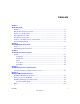
User Manual for the NETGEAR 7200 Series Layer 2 Managed Switch Software Figure 8-4 shows the RJ-45 plug and RJ-45 connector. Figure 8-4: RJ-45 Plug and RJ-45 Connector with Built-in LEDs Table 8-1 lists the pin assignments for the 10/100 Mbps RJ-45 plug and the RJ-45 connector. Table 8-1.
User Manual for the NETGEAR 7200 Series Layer 2 Managed Switch Software Table 8-2.
Appendix B Glossary Use the list below to find definitions for technical terms used in this manual. Numeric 802.1D The IEEE designator for Spanning Tree Protocol (STP). STP, a link management protocol, is part of the 802.1D standard for media access control bridges. Using the spanning tree algorithm, STP provides path redundancy while preventing endless loops in a network. An endless loop is created by multiple active paths between stations where there are alternate routes between hosts.
User Manual for the NETGEAR 7200 Series Layer 2 Managed Switch Software 100BASE-TX The IEEE specification for 100 Mbps Fast Ethernet over Category 5 twisted-pair cable. 1000BASE-SX The IEEE specification for 1000 Mbps Gigabit Ethernet over fiber-optic cable. 1000BASE-T The IEEE specification for 1000 Mbps Gigabit Ethernet over Category 5 twisted-pair cable. gain access. A Aging When an entry for a node is added to the lookup table of a switch, it is given a timestamp.
User Manual for the NETGEAR 7200 Series Layer 2 Managed Switch Software Baud The signaling rate of a line, that is, the number of transitions (voltage or frequency changes) made per second. Also known as line speed. BootP See “Bootstrap Protocol” on page 3. Bootstrap Protocol An Internet protocol that enables a diskless workstation to discover its own IP address, the IP address of a BootP server on the network, and a file to be loaded into memory to boot the machine.
User Manual for the NETGEAR 7200 Series Layer 2 Managed Switch Software CLI See “Command Line Interface” on page 4. Collision A term used to describe two colliding packets in an Ethernet network. Collisions are a part of normal Ethernet operation, but a sudden prolonged increase in the number of collisions can indicate a problem with a device, particularly if it is not accompanied by a general increase in traffic. Command Line Interface CLI is a line-item interface for configuring systems.
User Manual for the NETGEAR 7200 Series Layer 2 Managed Switch Software 198.105.232.4. The DNS system is, in fact, its own network. If one DNS server doesn't know how to translate a particular domain name, it asks another one, and so on, until the correct IP address is returned. Domain Name A descriptive name for an address or group of addresses on the Internet. Domain names are of the form of a registered entity name plus one of a number of predefined top level suffixes such as .com, .edu, .uk, etc.
User Manual for the NETGEAR 7200 Series Layer 2 Managed Switch Software Ethernet A LAN specification developed jointly by Xerox, Intel and Digital Equipment Corporation. Ethernet networks transmit packets at a rate of 10 Mbps. F Fast Ethernet An Ethernet system that is designed to operate at 100 Mbps.
User Manual for the NETGEAR 7200 Series Layer 2 Managed Switch Software G GARP See “Generic Attribute Registration Protocol” on page 7. GARP Information Propagation GIP is the propagation of information between GARP participants for the same application in a bridge is carried out by a GIP component.
User Manual for the NETGEAR 7200 Series Layer 2 Managed Switch Software GVRP See “GARP VLAN Registration Protocol” on page 7. H Half-duplex A system that allows packets to transmitted and received, but not at the same time. Contrast with full-duplex. I IEEE Institute of Electrical and Electronics Engineers. This American organization was founded in 1963 and sets standards for computers and communications. IETF Internet Engineering Task Force.
User Manual for the NETGEAR 7200 Series Layer 2 Managed Switch Software IP Multicasting Sending out data to distributed servers on the MBone (Multicast Backbone). For large amounts of data, IP Multicast is more efficient than normal Internet transmissions because the server can broadcast a message to many recipients simultaneously. Unlike traditional Internet traffic that requires separate connections for each source-destination pair, IP Multicasting allows many recipients to share the same source.
User Manual for the NETGEAR 7200 Series Layer 2 Managed Switch Software Local Area Network A communications network serving users within a limited area, such as one floor of a building. A LAN typically connects multiple personal computers and shared network devices such as storage and printers. Although many technologies exist to implement a LAN, Ethernet is the most common for connecting personal computers and is limited to a distance of 1,500 feet.
User Manual for the NETGEAR 7200 Series Layer 2 Managed Switch Software MDI/MDIX In cable wiring, the concept of transmit and receive are from the perspective of the PC, which is wired as a Media Dependant Interface (MDI). In MDI wiring, a PC transmits on pins 1 and 2. At the hub, switch, router, or access point, the perspective is reversed, and the hub receives on pins 1 and 2. This wiring is referred to as Media Dependant Interface - Crossover (MDI-X). See “Auto-negotiation” on page 2.
User Manual for the NETGEAR 7200 Series Layer 2 Managed Switch Software them, and are the only areas that can contain an ASBR. Compare with stub area. See also ASAM and OSPF. (Cisco Systems Inc.) O Open Systems Interconnection OSI is a seven (7) layer architecture model for communications systems developed by the ISO for the interconnection of data communications systems. Each layer uses and builds on the services provided by those below it. OSI See “Open Systems Interconnection” on page 12.
User Manual for the NETGEAR 7200 Series Layer 2 Managed Switch Software packet bound for or heading away from the first port will be forwarded onto the second port as well. The administrator places a protocol analyzer on the port receiving the mirrored data to monitor each segment separately. The analyzer captures and evaluates the data without affecting the client on the original port.
User Manual for the NETGEAR 7200 Series Layer 2 Managed Switch Software Using RADIUS, you must enter your user name and password before gaining access to a network. This information is passed to a RADIUS server, which checks that the information is correct, and then authorizes access. Though not an official standard, the RADIUS specification is maintained by a working group of the IETF.
User Manual for the NETGEAR 7200 Series Layer 2 Managed Switch Software SNMPsec (historic): Security is based on parties. Few, if any, vendors implemented this version of the protocol, which is now largely forgotten. SNMPv2p (historic): For this version, much work was done to update the SNMPv1 protocol and the SMIv1, and not just security. The result was updated protocol operations, new protocol operations and data types, and party-based security from SNMPsec.
User Manual for the NETGEAR 7200 Series Layer 2 Managed Switch Software STP Spanning Tree Protocol. See “802.1D” on page 1 for more information. stub area OSPF area that carries a default route, intra-area routes, and interarea routes, but does not carry external routes. Virtual links cannot be configured across a stub area, and they cannot contain an ASBR. Compare with non-stub area. See also ASAM and OSPF. (Cisco Systems Inc.
User Manual for the NETGEAR 7200 Series Layer 2 Managed Switch Software Trunking The process of combing a set of trunks that are traffic-engineered as a unit for the establishment of connections between switching systems in which all of the communications paths are interchangeable. U USP An abbreviation that represents Unit, Slot, Port. UTP Unshielded twisted pair is the cable used by 10BASE-T and 100BASE-Tx Ethernet networks.
User Manual for the NETGEAR 7200 Series Layer 2 Managed Switch Software Wide Area Network A WAN is a computer network that spans a relatively large geographical area. Typically, a WAN consists of two or more local-area networks (LANs). Windows Internet Naming Service WINS. Windows Internet Naming Service is a server process for resolving Windows-based computer names to IP addresses.
Index A Address Resolution Protocol.
config protocol vlan remove 7-34 config radius accounting mode 7-59 config radius accounting server add 7-60 config radius accounting server port 7-60 config radius accounting server remove 7-60 config radius accounting server secret 7-60 config radius maxretransmit 7-59 config radius server add 7-61 config radius server msgauth 7-62 config radius server port 7-61 config radius server primary 7-62 config radius server remove 7-61 config radius server secret 7-61 config radius timeout 7-59 config serial baud
port detailed 7-68 port maxrequests 7-67 port quietperiod 7-66 port reauthenabled 7-68 port reauthenticate 7-65 port reauthperiod 7-67 port servertimeout 7-67 port stats 7-69, 7-70 port summary 7-68 port transmitperiod 7-67 show port users 7-73 summary 7-68 supptimeout 7-67 downloading data types, setting 7-77 file names, setting 7-77 file paths, setting 7-77 IP addresses, setting 7-77 mode, setting 7-76 starting a transfer 7-78 //www.netgear.com/ 1-ii Hyper Terminal 4-2 I IEEE 802.
adding to LAGs 7-27 administrative mode 7-25 autoneg 7-26 deleting from LAGs 7-27 frame acceptance mode 7-32 GVRP 7-37 information 7-24 ingress filtering 7-33 lacp mode 7-26 link traps 7-25, 7-26 physical mode 7-26 statistics, related 201 commands 7-4, 7-9 tagging 7-31 VLAN IDs 7-32 VLAN information 7-32 adddest 7-45 addsrc 7-44 create 7-43 deldest 7-45 delsrc 7-44 remove 7-44 show 7-43 Management Access 2-1 management commands 201 commands 7-13 to 7-22 MDI/MDI-X 10-2 MDI/MDI-X wiring 10-11 mfdb gmrp 7-40
server stats 7-63 server summary 7-62 stats 7-65 summary 7-62 timeout 7-59 reset system command 7-79 root traps 7-21 routing default router IP address, setting 7-16 S save config command 7-58, 7-74 Security Commands 7-58 security commands 7-58 to 7-74 serial communication settings 7-15, 7-16 service port configuration 201 commands 7-16 sessions closing 7-58, 7-74 displaying 7-58 show commands show arp switch 7-3 show authentication login create 7-70 show authentication login delete 7-71 show authentication
show sysinfo 7-2 show telnet 7-22 show trapflags 7-20 show traplog 7-12 show users 7-56 show users authentication 7-74 show vlan detailed 7-29 show vlan interface 7-32 show vlan summary 7-29, 7-55 mst priority 7-53 mst summary 7-54 mst vlan add 7-53 mst vlan remove 7-53 port 7-47 port migrationcheck 7-48 port mode 7-48 summary 7-46 vlan 7-55 SNMP 2-2 speeds 7-26 SNMP communities access rights 7-17 adding 7-18 client IP masks 7-18 deleting 7-18 information 7-17 IP address 7-18 status 7-19 statistics por
TFTP setting as download mode 7-76 setting as upload mode 7-74 timeouts forwardingdb 7-23 serial 7-16 TIP 4-2 topology change notification traps 7-21 transfer commands transfer download datatype 7-77 transfer download filename 7-77 transfer download mode 7-76 transfer download path 7-77 transfer download serverip 7-77 transfer download start 7-78 transfer upload datatype 7-76 transfer upload filename 7-76 transfer upload mode 7-74 transfer upload path 7-75 transfer upload serverip 7-75 transfer upload start
X XMODEM setting as download mode 7-76 setting as upload mode 7-74 Z ZTerm 4-2 8 Index