RoHS Compliant Small Form Factor Pluggable Transceiver for Gigabit Ethernet and Fiber Channel AGM731F 350 E. Plumeria Drive San Jose, CA 95134-1911 USA 1-888-NETGEAR (638-4327) E-mail: info@NETGEAR.com www.NETGEAR.
RoHS Compliant Small Form Factor Pluggable Transceiver for Gigabit Ethernet and Fiber Channel FEATURES Compliant with SFP Transceiver MSA specification Compliant with Specifications for IEEE 802.3z/Gigabit Ethernet Compliant with the 1.0625GBd Fiber Channel FC-PI 100-M5-SN-I Rev.13 Compliant with Industry Standard RFT Electrical Connector and Cage Single + 3.
Absolute Maximum Ratings Parameter Storage Temperature Supply Voltage Symbol Ts VCC Min. -40 0 Typ. Max. 85 5 Unit ºC V Note Symbol TC VCC Min. -5 3.135 Typ. Max. 70 3.465 Unit ºC V Note Symbol ICCT Min. Typ. 180 Max. 300 Unit mA Note VDT VDISH VDISL VTXFH VTXFL 0.5 2 0 2 0 2.4 VCC+0.3 0.8 VCC+0.3 0.8 V V V V V 1 VDR VLOSH VLOSL tr / tf TJRX 0.35 2 0 2 VCC+0.3 0.
Optical Characteristics 7 (VCC=3.135V to 3.465V, Data Rate=1.25 Gb/sec, PRBS=2 -1 NRZ, 50/125µm or 62.5/125µm MMF) Parameter Transmitter Output Optical Power (Avg.) Optical Extinction Ratio Center Wavelength Spectral Width (RMS) Optical Rise/Fall Time Total Jitter (pk-pk) Relative Intensity Noise Output Eye Receiver Sensitivity (Avg.) Input Optical Wavelength LOS- De-Asserted (Avg.) LOS- asserted (Avg.) LOS-Hysteresis Overload Symbol Min. Typ. Max. Unit Note PO -9.
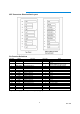
SFP Transceiver Electrical Pad Layout Pin Function Definitions Pin Num. 1 2 Name VeeT TX Fault Function Transmitter Ground Transmitter Fault Indication Plug Seq. 1 3 3 TX Disable Transmitter Disable 3 4 5 6 7 8 9 10 11 12 13 14 15 16 17 18 19 20 MOD-DEF2 MOD-DEF1 MOD-DEF0 Rate Select LOS VeeR VeeR VeeR RDRD+ VeeR VccR VccT VeeT TD+ TDVeeT Module Definition 2 Module Definition 1 Module Definition 0 Not Connect Loss of Signal Receiver Ground Receiver Ground Receiver Ground Inv.
Notes: 1) TX Fault is an open collector/drain output, which should be pulled up with a 4.7K – 10KΩ resistor on the host board. Pull up voltage between 2.0V and VccT, R+0.3V. When high, output indicates a laser fault of some kind. Low indicates normal operation. In the low state, the output will be pulled to < 0.8V. 2) TX disable is an input that is used to shut down the transmitter optical output. It is pulled up within the module with a 4.7 – 10 K Ω resistor. Its states are: 3) Low (0 – 0.
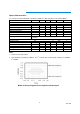
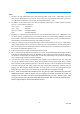
Package Outline Drawing for Metal Housing with Bail de-latch AGM731F 850nm 1.25GBd 1000Base-SX / LC Connector Class 1 Laser Proudct R Complies with 21 CFR 1040.10 and 1040.11 Made in China 272-10254-02 7 Rev.
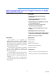
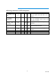
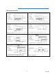
SFP timing parameters for SFP management Parameter Symbol TX_DISABLE Assert time t_off 10 TX_DISABLE Negate time t_on 1 Time to initialize, including reset of t_init TX_FAULT TX Fault Assert t_fault Time TX_DISABLE to t_rest reset LOS Assert Time t_loss_on LOS Deassert Time t_loss_off Serial ID Clock Rate f_serial_clock Min. Max.
SFP timing parameters Power on initialization of SFP transceiver, TX_DISABLE Power on initialization of SFP, TX_DISABLE asserted negated Initialization during hot plugging of SFP TRANSCEIVER. Example of initialization TX_DISABLE negated. during hot plugging, SFP TX_DISABLE timing during normal operation. Detection of transmitter safety fault condition Successful recovery from transient safety fault condition Unsuccessful recovery from safety fault condition Timing of LOS detection 9 Rev.
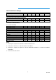
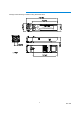
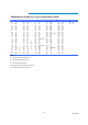
EEPROM Serial ID Memory Contents (2-Wire Address A0h) Address Hex ASCII Address Hex ASCII Address Hex ASCII Address Hex ASCII Address Hex ASCII Address Hex ASCII 00 03 25 41 A 50 20 75 SN 100 00 125 00 01 04 26 52 R 51 20 76 SN 101 00 126 00 02 07 27 20 52 20 77 SN 102 00 127 00 03 00 28 20 53 20 78 SN 103 00 04 00 29 20 54 20 79 SN 104 00 05 00 30 20 55 20 80 SN 105 00 06 01 31 20 56 41 81 SN 106 00 07 40 32 20 57 20 82 SN 107 00 08 40 33 20 58 20 83 SN 108 00 09 00 34 20 59 20 84 DC Note 3 109 00 10 00 35
Regulatory Compliance Feature Electromagnetic Interference (EMI) Reference Performance FCC CRF 47, Part15 Class B EN 55022 Class B (CISPR 22A) Radio Frequency Electromagnetic Field EN 61000-4-3 (1) Satisfied with electrical characteristics of product spec. IEC 61000-4-3 Electrostatic Discharge to the Duplex LC Receptacle EN 61000-4-2 (2) No physical damage IEC 61000-4-2 IEC 801.2 Electrostatic Discharge to the Electrical Pins MIL-STD-883E Method 3015.
© 2008 NETGEAR, Inc. NETGEAR, the NETGEAR Logo, NETGEAR Digital Entertainer Logo, Connect with Innovation, FrontView, IntelliFi, PowerShift, ProSafe, RAIDar, RAIDiator, X-RAID, RangeMax, ReadyNAS and Smart Wizard are trademarks of NETGEAR, Inc. in the United States and/or other countries. Other brand names mentioned herein are for identification purposes only and may be trademarks of their respective holder(s). Information is subject to change without notice. All rights reserved.