ReadyDATA 5200 Hardwa re M a nual 350 East Plumeria Drive San Jose, CA 95134 USA December 2012 202-11024-03
NETGEAR ReadyDATA 5200 Support Thank you for selecting NETGEAR products. After installing your device, locate the serial number on the label of your product and use it to register your product at https://my.netgear.com. You must register your product before you can use NETGEAR telephone support. NETGEAR recommends registering your product through the NETGEAR website. For product updates and web support, visit http://support.netgear.com. Phone (US & Canada only): 1-888-NETGEAR.
Table of Contents Chapter 1 Getting Started Front Panel . . . . . . . . . . . . . . . . . . . . . . . . . . . . . . . . . . . . . . . . . . . . . . . . . . 5 Rear Panel . . . . . . . . . . . . . . . . . . . . . . . . . . . . . . . . . . . . . . . . . . . . . . . . . . 7 Status and Shutdown . . . . . . . . . . . . . . . . . . . . . . . . . . . . . . . . . . . . . . . . . . 7 Boot Menu . . . . . . . . . . . . . . . . . . . . . . . . . . . . . . . . . . . . . . . . . . . . . . . . . . 9 Factory Settings . . .
1. 1 Getting Started Congratulations on your purchase of a NETGEAR® ReadyDATATM 5200. This ReadyDATA 5200 Hardware Manual describes the physical features of the ReadyDATA 5200. This chapter includes the following sections: • Front Panel • Rear Panel • Status and Shutdown • Boot Menu • Factory Settings • Technical Specifications This manual assumes that your ReadyDATA 5200 has been installed in a rack according to the instructions in the NETGEAR ReadyDATA 5200 Installation Guide.
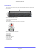
NETGEAR ReadyDATA 5200 Front Panel The following figure shows the front panel of the ReadyDATA 5200 with the optional front bezel removed. 1 2 Figure 1. ReadyDATA 5200 front panel 1. Drive bays with disk status LEDs 2. Control panel The following figure shows the control panel in more detail. 1 2 3 6 4 5 7 8 Figure 2. ReadyDATA 5200 control panel 1. Power button 2. Reset button 3. Power LED 4. Ethernet LED 5. Power diagnostic LED 6. Disk activity LED 7. Ethernet LED 8.
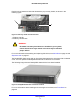
NETGEAR ReadyDATA 5200 Each drive bay features a latch that releases the pop-out tray handle, as shown in the following figure. 1 2 Figure 3. Disk tray handle and release latch 1. Disk tray handle 2. Disk tray release latch WARNING: No matter how many hard drives are installed in your system, ensure that all drive trays remain in the drive bays to maintain proper airflow. For more information about adding and replacing disk drives, see Add a Disk on page 23 and Replace a Disk on page 27.
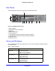
NETGEAR ReadyDATA 5200 Rear Panel The following figure shows the rear panel of the ReadyDATA 5200. 9 1 2 3 4 5 6 7 8 Figure 5. ReadyDATA 5200 rear panel 1. Power supplies 2. PS2 keyboard and mouse ports 3. USB ports 4. RS232 console port 5. VGA monitor port 6. 1-gigabit Ethernet ports with status LED status indicators 7. 10-gigabit Ethernet ports with status LED status indicators 8. SAS output port 9.
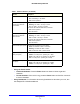
NETGEAR ReadyDATA 5200 Table 1. Status indicators (continued) Indicator Description Information LED The LED has these states: • On. Overheating or fan failure • Off. Normal operation Disk LEDs on disk tray with The top LED indicates disk activity as follows: SAS drives or SSD with • Blinking. The disk in the bay is active. SAS interface • On. The disk in the bay is inactive. The bottom LED indicates disk failure, as follows: • Off. Normal operation • On.
NETGEAR ReadyDATA 5200 Boot Menu Use the boot menu to restart or troubleshoot your ReadyDATA 5200. It has the following boot modes: • Normal. Initiates a normal boot process, just like booting using the Power button. • Factory default. Initiates a reboot process that resets the system to factory settings and clears all data. WARNING: This boot mode erases all data. If your system has data that you want to save, back it up to another storage device before performing a factory default reboot.
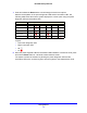
NETGEAR ReadyDATA 5200 7. Press and release the Reset button to scroll through the boot menu options. Watch the blink pattern of the power diagnostic LED and the information LED. The following table shows the how the system displays the current option using the power diagnostic LED and information LED.
NETGEAR ReadyDATA 5200 Factory Settings The following table lists factory settings for the ReadyDATA 5200. Table 2. Factory settings Feature Default Login User login URL when the ReadyDATA https://169.254.x.x 5200 is not connected to a DHCP server The last two octets are randomly generated based on the system’s MAC address.
NETGEAR ReadyDATA 5200 Technical Specifications The following table lists the technical specifications for the ReadyDATA 5200. Table 3.
2. 2 Expansion Disk Arrays This chapter describes physical features of the EDA2000 and EDA4000, which are optional expansion disk arrays you can use with the ReadyDATA 5200. This manual assumes that your expansion disk array has been installed in a rack according to the instructions in the NETGEAR ReadyDATA 5200 Installation Guide. The disk expansion arrays do not work independently; instead, they must be connected to a ReadyDATA 5200.
NETGEAR ReadyDATA 5200 Front Panel The following figure shows the front panel of the EDA2000 (2U expansion disk array), top, and EDA4000 (4U expansion disk array), bottom, with the optional front bezel removed. 2 1 2 Figure 6. EDA2000 front panel and EDA4000 front panel 1. Drive bays with disk status LEDs 2.
NETGEAR ReadyDATA 5200 The following figure shows the control panels in more detail. 1 1 2 2 3 6 4 5 7 8 3 6 7 4 8 5 Figure 7. EDA2000 and EDA4000 control panels 1. Power button 2. Reset button 3. Power LED 4. Ethernet LED 5. Power diagnostic LED 6. Disk activity LED 7. Ethernet LED 8. Information LED Each drive bay features a latch that releases the pop-out tray handle, as shown in the following figure. 1 2 Figure 8. Disk tray handle and release latch 1. Disk tray handle 2.
NETGEAR ReadyDATA 5200 For more information about adding and replacing disk drives, see Add a Disk on page 23 and Replace a Disk on page 27. The EDA 2000 and EDA 4000 come with an front bezel that protects the drive bays with a lockable cover. You can operate the EDA2000 and EDA4000 with or without the front bezel. For more information about installing and removing the front bezel, see Front Bezel on page 20.
NETGEAR ReadyDATA 5200 Status Information The status indicators on the EDA2000 and EDA4000 are the same as on the ReadyDATA 5200. For more information, see Table 1, Status indicators on page 7. Technical Specifications The following table lists the technical specifications for the EDA2000. Table 4.
NETGEAR ReadyDATA 5200 The following table lists the technical specifications for the EDA4000. Table 5. EDA4000 technical specifications Feature Specification Electrical Power supplies (PSU) Two 700W server-rated AC power supplies Input 100–240V AC, 50/60Hz Power consumption 170W typical with six 1-TB disks Thermal Cooling fans Five 80-mm dual ball-bearing chassis cooling fans Fan failure alerts Hardware LED, software using Dashboard and high temperature email alert with auto-shutdown option.
3. 3 Maintenance This chapter describes how to perform maintenance activities like adding disks and replacing disks and system components.
NETGEAR ReadyDATA 5200 Front Bezel The ReadyDATA 5200, EDA2000, and EDA4000 come with a front bezel that protects the drive bays with a lockable cover. You can operate these systems with or without the bezel. To install the front bezel: 1. Hold the bezel in front of the ReadyDATA 5200, EDA2000, or EDA4000 chassis. Ensure that the bezel is parallel to the chassis. 2. Insert the tabs on the right side of the bezel into the holes on the right bezel brace. 3.
NETGEAR ReadyDATA 5200 To remove the front bezel: 1. If the bezel is locked, unlock it. 2. Push the release latch on the left side of the bezel. 3. Pull the bezel toward you.
NETGEAR ReadyDATA 5200 Disks The ReadyDATA 5200 does not recognize non-NETGEAR disks. In addition, if you use non-NETGEAR disks, Dashboard might display an error. The ReadyDATA 5200 can recognize only disks that you obtain through NETGEAR or a NETGEAR authorized reseller. Failed Disk Notification When a disk fails in your ReadyDATA 5200, you are notified by email. Email alerts must be set up for notifications to be sent. In addition, Dashboard provides information about the failed disk.
NETGEAR ReadyDATA 5200 Add a Disk You can add a hard disk to an empty disk bay. You do not need to shut down your unit before adding a disk. You can use 2.5-inch and 3.5-inch disk drives in a ReadyDATA 5200, EDA2000, or EDA4000. To add a 2.5-inch disk: 1. Pull the disk tray release switch. The tray handle pops out. 2 1 1. Disk tray handle 2. Disk tray release switch 2. Pull out the disk tray.
NETGEAR ReadyDATA 5200 3. Turn the disk over and remove the metal plate from the drive tray. 4. (Optional) Depending on the thickness of the disk drive you are installing, adhere the foam pad to the metal plate in the area bounded by the metal tabs so that the 2.5-inch disk drive will rest on it. Use the foam pad to raise thin disk drives to the correct height so that you can install the screws. 5.
NETGEAR ReadyDATA 5200 6. Align the screw holes on the disk drive with the screw holes on the metal tabs and install the screws to fasten the disk drive to the metal plate. 7. With the disk tray handle to the right and the hard disk drive to the left, assemble the disk tray and metal plate. 8. Slide the disk tray into the unit and secure the handle.
NETGEAR ReadyDATA 5200 To add a 3.5-inch disk: 1. Pull the disk tray release switch. The tray handle pops out. 2 1 1. Disk tray handle 2. Disk tray release switch 2. Pull out the disk tray and place a disk in the tray. 3. Assemble the disk tray. Make sure that the hard disk connectors face the interior of the disk bay when you reassemble the disk. 4. Slide the disk tray into the unit and secure the handle.
NETGEAR ReadyDATA 5200 Replace a Disk If a disk fails, your system provides email alerts and status messages about the need to replace a disk. You do not need to power down your unit when replacing a disk. To replace a 2.5-inch disk: 1. If a disk failed, scan disk LEDs on the disk bays to identify the failed disk. 2. Pull the disk tray release pull switch. The tray handle pops out. 2 1 1. Disk tray handle 2. Disk tray release pull switch 3.
NETGEAR ReadyDATA 5200 4. Remove the screws that hold the disk drive to the metal tabs and remove the old disk drive. 5. Replace the disk drive and reassemble the disk tray. For more information, see Add a Disk on page 23. 6. Slide the disk tray back into the unit and secure the handle.
NETGEAR ReadyDATA 5200 To replace a 3.5-inch disk: 1. If a disk failed, scan disk LEDs on the disk bays to identify the failed disk. 2. Pull the disk tray release pull switch. The tray handle pops out. 2 1 1. Disk tray handle 2. Disk tray release pull switch 3. Pull out the disk tray, remove the screws, and remove the old disk drive. 4. Replace the disk drive and reassemble the disk tray. For more information, see Add a Disk on page 23. 5.
NETGEAR ReadyDATA 5200 System Components You can replace system components on your ReadyDATA 5200, EDA2000, or EDA4000. Power Supply If either of the two power supply modules fails, the other module takes the full load and allows the system to continue operation without interruption. The power diagnostic LED illuminates until the failed unit is replaced. You do not need to shut down the system to replace a power supply unit.
NETGEAR ReadyDATA 5200 WARNING: Ensure that the chassis cover is in place when the system is operating to allow proper cooling. Out-of-warranty damage to the system can occur if you do not strictly follow this practice. Fan If a fan fails, the remaining fans increase to full speed, the information LED on the control panel illuminates, and an email alert is sent to the system administrator. Replace a failed fan as soon as possible.
NETGEAR ReadyDATA 5200 Battery Your system uses a CR2032 battery. Dispose of used batteries according to the manufacturer’s instructions. DANGER: Installing the on-board battery upside down, which reverses its polarities, creates a danger of explosion. Take care to install the battery properly. To replace the battery: 1. Open the system and locate the battery holder. 2. Remove the old battery. 3. Install the new battery. Take care to install the new battery with the correct side up.
A. Warnings and Precautions A This appendix contains safety warnings and precautions for the ReadyDATA 5200 .
NETGEAR ReadyDATA 5200 Safety Warnings 1. The equipment is certified for installation only by trained personnel, according to the installation instructions provided with each unit. 2. The socket outlet shall be installed near the equipment and shall be easily accessible. 3. Observe the on-board battery precautions. Follow the battery replacement instructions in Battery on page 32. DANGER: Installing the on-board battery upside down, which reverses its polarities, creates a danger of explosion.
NETGEAR ReadyDATA 5200 • Do not use mats designed to decrease static electrical discharge as protection from electrical shock. Instead, use rubber mats that have been specifically designed as electrical insulators. • The power supply cords must include a grounding plug and must be plugged into grounded electrical outlets. General Safety Precautions Follow these rules to ensure general safety: • Keep the area around the ReadyDATA 5200 clean and free of clutter.
NETGEAR ReadyDATA 5200 Electrostatic Discharge (ESD) Precautions Electrostatic discharge is generated by two objects with different electrical charges coming into contact with each other. An electrical discharge is created to neutralize this difference, which can damage electronic components and printed circuit boards.
B. Notification of Compliance B Regulatory Compliance Information This section includes user requirements for operating this product in accordance with National laws for usage of radio spectrum and operation of radio devices. Failure of the end-user to comply with the applicable requirements may result in unlawful operation and adverse action against the end-user by the applicable National regulatory authority.
NETGEAR ReadyDATA 5200 FCC Declaration Of Conformity We, NETGEAR, Inc., 350 East Plumeria Drive, San Jose, CA 95134, declare under our sole responsibility that the NETGEAR ReadyDATA 5200 complies with Part 15 of FCC Rules. Operation is subject to the following two conditions: • This device may not cause harmful interference, and • This device must accept any interference received, including interference that may cause undesired operation.