Start Here Congratulations on your purchase of the NETGEAR™ Model EN104TP, Model EN106TP, or Model EN108TP Ethernet hub. The hubs deliver standards-based, plug-and-play networking solutions for small businesses, home offices, and lowdensity workgroups of larger companies. In this installation guide, all three hubs are referred to collectively as the Model EN104TP/EN106TP/EN108TP hub. Each hub is listed individually when information is provided that refers to a specific model.
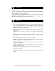
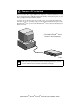
Package Contents Model EN104TP hub 10 BASE-T HUB or Model EN106TP hub 10 BASE-T HUB EN104TP Model EN108TP hub or EN106TP 10 BASE-T HUB Link/Rx Partition Pwr Normal/Uplink Col Pwr EN108TP Col 1 2 3 4 5 6 Mounting kit 1 2 3 4 5 6 7 8 Power adapter and cord Installation guide, Warranty & Owner Registration Card 8722FA Verify that your package contains the following: • Model EN104TP hub, Model EN106TP hub, or Model EN108TP hub • Mounting kit (for wall installation) • This in
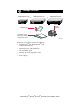
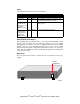
Product Illustration Front Panel of the Model EN104TP hub 10BASE-T ports 10 BASE-T HUB Pwr (Power) Col (Collision) EN104TP LINK Pwr Rx Col Normal/Uplink push button Front Panel of the Model EN106TP hub 10 BASE-T HUB EN106TP LINK Pwr Rx Normal/Uplink Col 1 2 3 4 5 6 Front Panel of the Model EN108TP hub 10 BASE-T HUB Pwr EN108TP LINK Rx Col 1 2 3 4 5 6 7 8 8723FA Vista 10BASE-T Network Ports with Built-in LEDs The front panel of the Model EN104TP hub has four RJ-45 10BASE
LEDs The table below describes the activity of the LEDs. Label Color Activity Description Pwr (Power) Green On Col (collision) Amber Blinking Data collision is occurring on the network. Note that occasional collisions are normal. Green Link (located on the top left corner of each vista 10BASE-T port) Rx (located on the top right corner of each vista 10BASE-T port) Green On Power is supplied to the hub. The link between this port and the connected device is good.
Installation Procedures Prepare the Site Before you begin installing your hub, prepare the installation site. Make sure your operating environment meets the operating environment requirements of the equipment. Characteristic Requirement Temperature Ambient temperature between 0° and 40° C (32° and 104° F). No nearby heat sources such as direct sunlight, warm air exhausts, or heaters. Operating humidity Maximum relative humidity of 90%, noncondensing. Ventilation Minimum 2 inches (5.
Connect a PC to the Hub You can connect PCs, Apple Macintosh computers, UNIX workstations, or any device equipped with a 10BASE-T Ethernet interface to the RJ-45 ports on your hub by using twisted pair Ethernet cables. To connect any of the RJ-45 ports on your hub to a PC, use a regular straight-through UTP cable. If you are connecting using port 4 on the Model EN104TP hub, port 6 on the Model EN106TP hub, or port 8 on the Model EN108TP hub, set the Normal/Uplink push button to Normal.
Connect the Hub to a Network Cascading refers to connecting hubs together to increase the number of ports or the number of users supported on the network. The 10BASE-T ports can be used to cascade hubs together. The twisted pair cable extended from a 10BASE-T port (or UTP port) is called a twisted pair segment and can be up to 100 meters (m) in length.
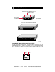
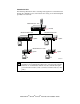
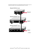
Cascade the Hub The following illustration shows cascading hubs together in a hierarchical star through the 10BASE-T ports and indicates the setting of the Normal/Uplink push button on each hub.
The following illustration shows cascading hubs together daisy-chain style and indicates the setting of the Normal/Uplink push button on each hub.
Verify the Installation To complete the installation, connect the power cord first to the power receptacle on the hub rear panel and then to the power outlet on the wall. When power has been applied to the hub: • The green Pwr (Power) LED on the front panel is on. • The green Link LED on each connected port is on. If there are any problems, refer to “Troubleshooting Information.
Troubleshooting Information Refer to this table and the information that follows the table to troubleshoot your hub. Symptom Cause Solution Amber Col LED blinks. There is data collision on the network. Data collision is normal on Ethernet networks. No action is required. Amber Col LED blinks excessively. There is data collision Make sure connected devices are operating in half-duplex mode. The hub on the network because the network is is not compatible with devices that operate in full-duplex mode.
Technical Specifications Cable and Connector Information Twisted Pair Cables For two devices to communicate, the transmitter of each device must be connected to the receiver of the other device. The crossover function is usually implemented internally as part of the circuitry in the device. Most ports on switches and repeaters have media-dependent interfaces with crossover ports. These ports are referred to as MDI-X or Normal ports.
RJ-45 Connector The RJ-45 connector (shown in the illustration with an RJ-45 plug) is used to connect workstations, hubs, and switches through unshielded twisted pair cable. The RJ-45 connector accepts four-pair Category 3 or Category 5 UTP cable. Only two pairs are used for 10BASE-T wiring.
Technical Specifications General Specifications Network Protocol and Standards Compatibility IEEE 802.3i, 10BASE-T Ethernet Data Rate 10 Mbps, Manchester encoded Interface 4 10BASE-T ports (RJ-45) on the Model EN104TP hub 6 10BASE-T ports (RJ-45) on the Model TP EN106 hub 8 10BASE-T ports (RJ-45) on the Model EN108TP hub Power Power Consumption: 3.5 W Model EN104TP hub Model EN106TP hub 7.2 W Model EN108TP hub 13.7 W DC output voltage (Power adapter): 5V DC @ 800 mA max.
Safety Agency Approvals for Power Adapter CE mark, commercial UL listed (UL 1950) CSA certified (CSA 22.
© 1998 by NETGEAR, Inc. All rights reserved. Trademarks Bay Networks is a registered trademark of Bay Networks, Inc. NETGEAR is a trademark of Bay Networks, Inc. All other trademarks and registered trademarks are the property of their respective owners. Statement of Conditions In the interest of improving internal design, operational function, and/or reliability, NETGEAR reserves the right to make changes to the products described in this document without notice.
NETGEAR, Inc. A Bay Networks Company 4401 Great America Parkway Santa Clara, CA 95054 USA Phone: 888-NETGEAR Customer Support Phone Australia: 1800-142-046 France: 0800-90-2078 Germany: 0130-817305 Japan: 0120-66-5402 Korea: 00308-11-0319 New Zealand: 0800-444-626 Sweden: 020-790086 United Kingdom: (44) 171-571-5120 U.S./Canada: 800-211-2069 Internet/World Wide Web The NETGEAR Web page is at http://NETGEAR.baynetworks.com. Defective or damaged merchandise can be returned to your point-of-sale.