Start Here The NETGEAR™ Model FS516 16-Port Fast Ethernet Switch and Model FS524 24-Port Fast Ethernet Switch provide you with a low-cost, high-performance network solution and are designed to support power workgroups operating at either 10 megabits per second (Mbps) or 100 Mbps. Ethernet switches provide private, dedicated, 10 Mbps (or 100 Mbps) capacity to each connected PC/server or hub/workgroup segment, which is significantly higher than in a shared environment.
• Normal/Uplink push button to simplify network extension The switch can be connected to a hub using a simple, straight-through cable.
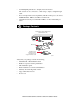
Product Illustration Front Panel The front panel of the Model FS516/FS524 switch contains the following LEDs that correspond to each network port located on the hub: Rx/Tx/Collision and 100 Mbps. Each vista RJ-45 network port has its own Link LED (located at the top left corner of each 10/100 Mbps port), and full-duplex (FDX) LED (located at the top right corner of each 10/100 Mbps port).
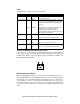
LEDs The table below describes the activity of the LEDs. Label Color Activity Description Pwr (Power) Green On Off Power is supplied to the switch. Power is disconnected. Rx/Tx/Collision Green Blinking Packet transmission or reception is occurring on the port. The blinking action corresponds to the number of packets that are transmitted or received. Yellow Blinking Data collisions are occurring on the port. The blinking corresponds to the number of collisions.
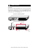
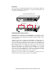
Rear Panel The rear panel of the Model FS516/FS524 switch has full-duplex (FDX) and auto-duplex (AUTO) toggle switches, fans for cooling, and a standard AC power receptacle for the supplied power cord. Rear Panel of the Model FS516 Switch AUTO FDX - Enable port to determine duplex mode automatically Force port to operate at Full Duplex and Half Duplex mode only 1 10/100 Mbps 8 1 8 FDX AUTO 100-240 VAC 50-60 Hz 0.
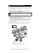
. Applications The Model FS516/FS524 switch is designed to provide flexibility in configuring your network connections. Each switch can be used as a standalone device or can be used with 10 Mbps or 100 Mbps hubs or other interconnection devices in various configurations. The configuration examples in this section illustrate the integration of the switches in network environments of all sizes and types.
Prepare the Site Before you begin installing your switch, prepare the installation site. Make sure your operating environment meets the operating environment requirements of the equipment. Characteristic Requirement Temperature Ambient temperature between 0° and 40° C (32° and 104° F). No nearby heat sources such as direct sunlight, warm air exhausts, or heaters. Operating humidity Maximum relative humidity of 90%, noncondensing. Ventilation Minimum 2 inches (5.08 cm) on all sides for cooling.
Connect Devices to the Switch Before connecting the switch, be sure you review “Applications” for information about determining the appropriate configuration for your networking needs. To connect the switch: 1. Connect the devices to the 10/100 Mbps ports on the switch, using Category 5 UTP cable and an RJ-45 plug. Note: Ethernet specifications limit the cable length between your PC or server and the switch to 328 feet (100 meters) in length. 2. Set the Normal/Uplink push button. 3.
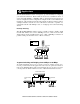
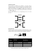
Twisted Pair Cables For two devices to communicate, the transmitter of each device must be connected to the receiver of the other device. The crossover function is usually implemented internally as part of the circuitry in the device. Most ports on switches and repeaters have media-dependent interfaces with crossover ports. These ports are referred to as MDI-X or normal ports. Computer and workstation adapter cards are usually media-dependent interface ports referred to as MDI or uplink ports.
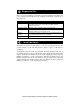
Verify Installation When power has been applied to the switch: • • The green Pwr (Power) LED on the front panel is on. The green Link LED on each connected port is on. When the switch is connected and operating, refer to the table in “LEDs” for information about the LEDs and their activity. Troubleshooting Information Symptom Cause Solution Power LED is off. No power is received at the hub. Check the power cord connections for the switch and the connected device.
Technical Specifications General Specifications Network Protocol and Standards Compatibility Model FS516 Fast Ethernet Switch Model FS524 Fast Ethernet Switch ISO/IEC 802-3 (ANSI/IEEE 802.3i) 10BASE-T Ethernet IEEE 802.
© 1999 by NETGEAR, Inc. All rights reserved. Trademarks Bay Networks is a registered trademark of Bay Networks, Inc. NETGEAR is a trademark of Bay Networks, Inc. All other trademarks and registered trademarks are the property of their respective owners. Statement of Conditions In the interest of improving internal design, operational function, and/or reliability, NETGEAR reserves the right to make changes to the products described in this document without notice.
Canadian Department of Communications Radio Interference Regulations This digital apparatus (NETGEAR Model FS516/FS524 Fast Ethernet Switch) does not exceed the Class A limits for radio-noise emissions from digital apparatus as set out in the Radio Interference Regulations of the Canadian Department of Communications.
NETGEAR, Inc. A Bay Networks Company 4401 Great America Parkway Santa Clara, CA 95054 USA Phone: 888-NETGEAR http://WWW.NETGEARinc.