© 2004 by NETGEAR, Inc. All rights reserved. Trademarks @2004 NETGEAR, Inc. NETGEAR, the Netgear logo, The Gear Guy and Everybody’s connecting are trademarks of Netgear, Inc. in the United States and/or other countries. Other brand and product names are trademarks of their respective holders. Information is subject to change without notice. All rights reserved.
CONTENTS Trademarks .....................................................................................................................................................................................1 Statement of Conditions ....................................................................................................................................................................1 CHAPTER 1: SWITCH MANAGEMENT OVERVIEW .................................................................................
CHAPTER 1: SWITCH MANAGEMENT OVERVIEW This chapter gives an overview of switch management, including the methods you can use to manage your NETGEAR Smart Switch series. Topics include Management Access Overview Management Access Overview Your NETGEAR Smart Switch contains software for viewing, changing, and monitoring the way it works. This management software is not required for the switch to work. You can use the 10/100 Mbps ports and the built-in Gigabit ports without using the management software.
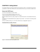
CHAPTER 2: Getting Started This chapter will walk you through the steps to start managing your switch. This chapter will cover how to get started in a network with a DHCP server (most common) as well as if you do not have a DHCP server. Network with DHCP server: Connect the Smart Switch to a DHCP network. Power on the Smart Switch by plugging in power cord. Install the Smartwizard Discovery program on your computer Start the Smartwizard Discovery utility.
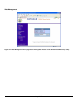
Smartwizard Discovery > Web Access Figure 2-2. Web Access 7. Start managing your switch via your web browser. The default password is ‘password’. Web Management Figure 2-3.
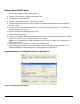
Network without DHCP server 1. Connect your switch to your existing network. 2. Power on your switch by plugging in the power cord. 3. The default IP is 192.168.0.239. 4. Install the Smartwizard Discovery program on your PC. 5. Start the Smartwizard Discovery utility. Chapter 4 has detailed instructions on the Smartwizard Discovery utility. 6. Click Discover on the Smartwizard Discovery main screen to find your switch. You should see a something similar to Figure 2-1. 7.
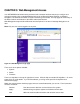
Web Management Figure 2-7.
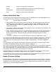
CHAPTER 3: Web Management Access Your NETGEAR Smart Switch series provides a built-in browser interface that lets you configure and manage it remotely using a standard Web browser such as Microsoft Internet Explorer or Netscape Navigator. This interface also allows for system monitoring of the switch. The help page will cover many of the basic functions and features of the switch and its web interface. Web Management requires either Microsoft Internet Explorer 5.0 or later or Netscape Navigator 6.
Browse: Locates a certain path for a desired file. Delete: Deletes selected entries from table and refreshes screen data Factory Reset: Restore the system factory default value. Help: Goes to relevant section of Help Menu System> Switch Status Page The Switch Status page displays the port settings for both 10/100 Mbps and 10/100/1000 Mbps ports. To configure the ports, go to the Switch> Port Configuration page. • ID: • Speed: Indicates the communication mode set for the port.
Note: Once this new IP access is enabled, you can only access the switch via this IP. Make sure that your new IP is the same of current PC. System> Set-up Page This page will allow access to the system information parameters. • Enter System Name and Location Name • The DHCP function is enabled by default. Click Static IP Address to disable the DHCP function.
10 Mbps full duplex (10M Full), 100 Mbps half duplex (100M Half), 100 Mbps full duplex (100M Full), or Disable. • Flow Control: Indicates whether Flow Control support is set for on (Enabled) or off (Disabled). The default setting for all ports is enabled. • QOS: Indicate the priority for the port. The default setting for all ports is Normal. Quality of Service (QoS) is a way of managing traffic in a network, by treating different types of traffic with different levels of service priority.
Switch> Statistics Page The Statistics Table shows the statistics types for one port over time. • ID: • Tx: Transmitted packet/s. • Rx: Received packet/s. • Tx Error: Transmitted packet/s with error. • Rx Error: Received packet/s with error. The port number on the switch Packets are counted as TX Error if they: • Had a late collision detected during the transmission (512 bit-times into the transmission). • Experienced 16 failed transmission attempts due to collision.
Switch> VLAN> Port-based VLAN Depending on your model, there are up to 26 port-based VLAN groups supported on this switch, any one port can belong to different VLAN groups. The default VLAN group port-based VLAN that have all ports belonging to VLAN 1. Change members • Click a VLAN ID as shown in Figure 5-16 • Click to select port/s for VLAN members • Click Apply to activate the new setting Add VLAN • Click Add VLAN.
Add a port to a VLAN Group • Under the VLAN ID drop down menu, select the VLAN you want to edit. • Click the box below the port number so that a ‘T’ (tagged) or ‘U’ (untagged) appears. • Click Apply. Remove a port from a VLAN Group • Click the box again until a blank box appears. This will remove VLAN membership from the port. • Click Apply. Note: The default PVID of all ports is 1; therefore, you cannot remove any ports for the default Tag VLAN.
Switch> Trunking Page Port Trunking is a feature that allows multiple links between switches to work as one virtual link (aggregate link). Trunks can be defined for similar port types only. For example, a 10/100 port cannot form a Port Trunk with a gigabit port. For 10/100 ports, trunks can only be formed within the same bank. A bank is a set of eight ports, such as ports 1 to 8, ports 9 to 16, ports 17 to 24, or port 25 and port 26, on the same switch unit.
• Configuration Backup • Factory Reset Firmware> Configuration Backup Page You can backup the system and switch settings to your workstation. This can help you to reconfigure the switch quickly if you have to re-set to factory defaults. Additionally, if you want to try out different configurations on the switch, this feature will enable you to quickly return to a previous configuration.
CHAPTER 4: Software Upgrade Procedure The application software for the Smart Switch is upgradeable, enabling your switch to take advantage of improvements and additional features as they become available. The upgrade procedure and the required equipment are described in the following section. The upgrade procedure is as follows: 1. Save the new firmware to your computer. 2. Start the Smartwizard Discovery utility program. 3. Select your switch by clicking on it. 4.
Figure 3-3. Enter Password and click Start. Note: Once the system finishes firmware upgrade process, the switch will automatically reboot. The Smartwizard Discovery utility will determine success of upgrade process based on the success of the system reboot.
APPENDIX A: DEFAULT SETTINGS This appendix provides default settings for the NETGEAR Smart Switches. You can always configure the switch to default settings by using the Factory Reset function from a Web browser. Table A-1.
APPENDIX B: IEEE 802.1Q VLAN A Local Area Network (LAN) can generally be defined as a broadcast domain. Hubs, bridges or switches in the same physical segment or segments connect all end node switches. End nodes can communicate with each other without the need for a router. Routers connect LANs together, routing the traffic to appropriate port.
Packets leaving the switch will be either tagged or untagged depending on the setting for that port’s VLAN membership properties. A ‘U’ for a given port means that packets leaving the switch from that port will be Untagged. Inversely, a ‘T’ for a given port means that packets leaving the switch from that port will be tagged with the respective VLAN ID in which it participated in.
APPENDIX C: Port-based VLAN Port-based VLAN will help efficiently confine the broadcast traffic to the switch ports. This switch allows up to 26 port-based VLAN groups, any one port can belong to different VLAN groups. The default VLAN group port-based VLAN that have all ports belonging to VLAN 1. Port-based VLANs Packets received by the switch will be treated in the following way: o When a packet enters a port, it only can proceed to the VLAN which the port belongs to.
If a Marketing user sends out a broadcast message, the Sales and Accounting departments will not be affected by the message, as it will not go out on their ports. Only the Marketing department and the IT group will get the broadcast message. If an IT user sends out a broadcast message, everyone will get it.