© 2005 by NETGEAR, Inc. NETGEAR, the Netgear logo, Auto Uplink, ProSafe and Everybody's connecting are trademarks or registered trademarks of Netgear, Inc. in the United States and/or other countries. Other brand and product names are the trademarks of their respective holders. Information is subject to change without notice. All rights reserved.
Canadian Department of Communications Radio Interference Regulations This digital apparatus (NETGEAR Model FSM726 Managed Switch) do not exceed the Class A limits for radio-noise emissions from digital apparatus as set out in the Radio Interference Regulations of the Canadian Department of Communications.
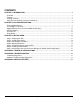
CONTENTS CHAPTER 1: INTRODUCTION...................................................................................................................................5 Overview....................................................................................................................................................................5 Features.....................................................................................................................................................................
Figures FIGURE 1-1. PACKAGE CONTENTS ......................................................................................................... 8 FIGURE 2-1. FRONT PANEL OF THE FSM726 MANAGED SWITCH ........................................................ 9 FIGURE 2-2. BACK PANEL OF THE FSM726 MANAGED SWITCH........................................................... 9 FIGURE 2-3. WARNING! CREATING REDUNDANT PATHS BETWEEN NETWORK DEVICES............. 10 FIGURE 3-1. ATTACHING MOUNTING BRACKETS ................
CHAPTER 1: INTRODUCTION Congratulations on your purchase of a NETGEAR Model FSM726 Managed, Fast Ethernet Switch! Your NETGEAR Switch is a state-of-the-art, high-performance, IEEE-compliant network solution designed for users who want ease of use along with the power of management to eliminate bottlenecks, boost performance, and increase productivity. This Installation Guide will assist you in getting your switch up and running.
Features • The following list identifies the key features of the NETGEAR Model FSM726 Managed Switch. • Twenty-four 10/100 Mbps auto sensing Fast Ethernet switching ports • Two Gigabit Ethernet ports that can be used either through the built-in RJ-45 ports for 10/100/1000 Mbps connectivity or through the GBIC modules for a variety of fiber connections • Full compatibility with IEEE standards: o o o o • Full Layer 2 switch management including: o o o o o o o o o • IEEE 802.
• Automatic address learning function to build the packet-forwarding information table. The table contains up to 8,000 media access control (MAC) addresses (that is, the switch can support networks with as many as 8,000 devices).
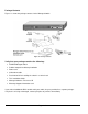
Package Contents Figure 1-1 shows the package contents for the Managed Switch. Figure 1-1.
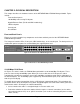
CHAPTER 2: PHYSICAL DESCRIPTION This chapter describes the hardware features of the NETGEAR Model FSM726 Managed Switch. Topics include: Front and back panels 10/100 Mbps auto-sensing RJ-45 ports Gigabit Ethernet Ports (RJ-45 and GBIC module bay) LED descriptions Console port Reset Button Front and Back Panels Figures 2-1 and 2-2 show the key components on the front and back panels of the NETGEAR Model FSM726 Managed Switch The front panel contains LEDs, RJ-45 jacks, GBIC module bays, and a console port.
• After ascertaining this information, the switch automatically configures the RJ-45 port to enable communications with the attached device, without requiring user intervention. In this way, the Auto Uplink technology compensates for setting uplink connections, while eliminating concern about whether to use crossover or straight-through cables when attaching devices. Warning! You must use Link Aggregation (a.k.a. Port Trunking) to create multiple links between switches.
LED Descriptions The front panel of the NETGEAR Model FSM726 Managed Switch has LEDs that provide a quick and accurate display of port speed and activity. The Gigabit Ethernet ports also have LEDs that show link and mode status. Table 2-1 summarizes the LEDs on the switch and Gigabit Ethernet module. Table 2-1.
In addition to using the console port, you can manage the switch using a Web browser or a Simple Network Management Protocol (SNMP) management program. Note: You must use the console port for the initial management configuration. For more information about console-port connections, see “Connecting to the Console Port” in Chapter 3 Installation. For more information about managing the switch, see the User Manual located on the CDROM.
CHAPTER 3: INSTALLATION This chapter describes the installation procedures for your NETGEAR Model FSM726 Managed Switch.
Step 2: Installing the Switch You can install your NETGEAR Model FSM726 Managed Switch on a flat surface or in a standard 19-inch rack. Installing the Switch on a Flat Surface The switch ships with four self-adhesive rubber footpads. Stick one rubber footpad on each of the four concave spaces on the bottom of the switch. The rubber footpads cushion the switch against shock/vibrations. Installing the Switch in a Rack To install the switch in a rack, use the following procedure (and refer to Figure 3-1).
cord, select an AC outlet that is not controlled by a wall switch, which can turn off power to the switch. After you select an appropriate outlet, use the following procedure to apply AC power. 1. Connect the female end of the supplied AC power adapter cable to the power receptacle on the back of the switch. 2. Connect the 3-pronged end of the AC power adapter cable to a grounded 3-pronged AC outlet.
2. After the switch has been configured for management (Step 7), use one of the management interfaces (web browser or console interface) to configure the port with the GBIC module installed to the GBIC option. 3. To install a second Gigabit Ethernet module, repeat this procedure using the second module and the unoccupied module bay. Figure 3-3.
Parity: none Stop bit: 1 Flow control: none 4. Hit the return key, and the below screen should appear. Figure 3-4. System Information 5. If you want to use your web browser, or telnet session to manage your switch, note the IP address on this page. To use your web browser, simply type the IP address in the URL address bar and hit enter.
2. Select ‘C’ for Set-up 3. Select ‘B’ for IP configuration 4. Enter in the IP address, Subnet mask, and Default Gateway 5. Hit ‘Q’ twice to exit to the main menu 6. Select ‘D’ for the Tools page 7. Select ‘A’ for Save Configurations to NVRAM, and confirm with a ‘Y’ 8. Select ‘C’ for Reset Switch, and confirm with a ‘Y’ To continue using the console interface to manage your switch, e.g. set GBIC ports, hit ‘ESC’ to go to the main menu. To set the GBIC ports, go to Set-up, then Port Configuration.
APPENDIX A: TECHNICAL SPECIFICATIONS This appendix provides technical specifications for the NETGEAR Model FSM726 Managed Switch. Network Protocol and Standards Compatibility IEEE 802.3i 10BASE-T IEEE 802.3u 100BASE-TX IEEE 802.3z 1000BASE-SX IEEE 802.3ab 1000BASE-T IEEE 802.3x flow control Management IEEE 802.1Q Static VLAN (Up to 64) IEEE 802.1p Class of Service (CoS) IEEE 802.1D Spanning Tree Protocol Port Trunking - Manual as per IEEE802.
Power Supply DC power consumption: 15 W maximum 100-240VAC/50-60 Hz universal input Physical Dimensions 440 x 205 x 43 mm (W x D x H) 17.3 x 8.1 x 1.
APPENDIX B: TROUBLESHOOTING This chapter provides information about troubleshooting the NETGEAR Model FSM726 Managed Switch. Topics include: o Troubleshooting chart o Additional troubleshooting suggestions Troubleshooting Chart Table B-1 lists symptoms, causes, and solutions of possible problems. Table B-1. Troubleshooting Chart Symptom Cause Solution Power LED is off. No power is received Link LED is off or intermittent. Port connection is not working.
Configuration If problems occur after altering the network configuration, restore the original connections and determine the problem by implementing the new changes, one step at a time. Make sure that cable distances, repeater limits, and other physical aspects of the installation do not exceed the Ethernet limitations. Switch Integrity If required, verify the integrity of the switch by resetting the switch.
APPENDIX C: Default Settings This appendix provides the default settings for the NETGEAR Model FSM726 Managed Switch. Feature FSM726 Default Setting Port Speed Port Duplex Flow Control (half duplex) Flow Control (full duplex) Broadcast Storm Control Gigabit ports IP Configuration Password protection User Name Password VLAN IP Multicast Filtering Spanning Tree Protocol Fast Link Traffic Prioritization 802.