
Quick Reference Guide

Reference Manual for the Model FVS318 Broadband ProSafe VPN Firewall
2-6 Introduction
M-10146-01
These LEDs are green when lit, except for the TEST LED, which is amber.
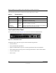
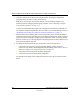
The Firewall’s Rear Panel
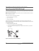
The rear panel of the FVS318 (Figure 2-2) contains the connections identified below.
Figure 2-2: FVS318 Rear Panel
Viewed from right to left, the rear panel contains the following elements:
• Ground connector.
• Factory Default Reset push button.
• Eight Local Ethernet RJ-45 ports for connecting the firewall to the local computers.
• Internet WAN Ethernet RJ-45 port for connecting the firewall to a cable or DSL modem.
• AC power adapter input.
• Power switch.
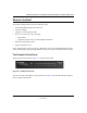
Table 2-1: LED Descriptions
Label Activity Description
POWER On Power is supplied to the firewall.
TEST On
Off
The system is initializing.
The system is ready and running.
INTERNET and LOCAl
100 On/Blinking The port is operating at 100 Mbps.
LINK/ACT
(Link/Activity)
On/Blinking The port has detected a link with a connection and is operating at
10 Mbps. Blinking indicates data transmission.