Reference Manual for the ProSafe Wireless 802.11g Firewall/Print Server Model FWG114P Troubleshooting the Web Configuration Interface If you are unable to access the router’s Web Configuration interface from a PC on your local network, check the following: • Check the Ethernet connection between the PC and the router as described in the previous section. • Make sure your PC’s IP address is on the same subnet as the router.
Reference Manual for the ProSafe Wireless 802.11g Firewall/Print Server Model FWG114P Troubleshooting the ISP Connection If your router is unable to access the Internet, you should first determine whether the router is able to obtain a WAN IP address from the ISP. Unless you have been assigned a static IP address, your router must request an IP address from the ISP. You can determine whether the request was successful using the Web Configuration Manager. To check the WAN IP address: 1.
Reference Manual for the ProSafe Wireless 802.11g Firewall/Print Server Model FWG114P OR Configure your router to spoof your PC’s MAC address. This can be done in the Basic Settings menu. Refer to “Manually Configuring Your Internet Connection” on page 3-11. If your router can obtain an IP address, but your PC is unable to load any web pages from the Internet: • Your PC may not recognize any DNS server addresses.
Reference Manual for the ProSafe Wireless 802.11g Firewall/Print Server Model FWG114P If the path is working, you see this message: Reply from < IP address >: bytes=32 time=NN ms TTL=xxx If the path is not working, you see this message: Request timed out If the path is not functioning correctly, you could have one of the following problems: • Wrong physical connections — Make sure the LAN port LED is on. If the LED is off, follow the instructions in “LAN or Internet Port LEDs Not On” on page 9-2.
Reference Manual for the ProSafe Wireless 802.11g Firewall/Print Server Model FWG114P — If your ISP assigned a host name to your PC, enter that host name as the Account Name in the Basic Settings menu. — Your ISP could be rejecting the Ethernet MAC addresses of all but one of your PCs. Many broadband ISPs restrict access by only allowing traffic from the MAC address of your broadband modem, but some ISPs additionally restrict access to the MAC address of a single PC connected to that modem.
Reference Manual for the ProSafe Wireless 802.
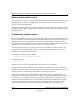
Appendix A Technical Specifications This appendix provides technical specifications for the ProSafe Wireless 802.11g Firewall/Print Server Model FWG114P. Network Protocol and Standards Compatibility Data and Routing Protocols: TCP/IP, RIP-1, RIP-2, DHCP PPP over Ethernet (PPPoE) Power Adapter North America: 120V, 60 Hz, input United Kingdom, Australia: 240V, 50 Hz, input Europe: 230V, 50 Hz, input Japan: 100V, 50/60 Hz, input All regions (output): 12 V DC @ 1.
Reference Manual for the ProSafe Wireless 802.11g Firewall/Print Server Model FWG114P Electromagnetic Emissions Meets requirements of: FCC Part 15 Class B VCCI Class B EN 55 022 (CISPR 22), Class B Interface Specifications LAN: 10BASE-T or 100BASE-Tx, RJ-45 WAN: 10BASE-T or 100BASE-Tx Wireless Data Encoding: Direct Sequence Spread Spectrum (DSSS) Maximum Computers Per Wireless Network: Limited by the amount of wireless network traffic generated by each node. Typically 30-70 nodes. 802.
Appendix B Networks, Routing, and Firewall Basics This chapter provides an overview of IP networks, routing, and firewalls. Related Publications As you read this document, you may be directed to various RFC documents for further information. An RFC is a Request For Comment (RFC) published by the Internet Engineering Task Force (IETF), an open organization that defines the architecture and operation of the Internet.
Reference Manual for the Model FVS318 Broadband ProSafe VPN Firewall Routing Information Protocol One of the protocols used by a router to build and maintain a picture of the network is the Routing Information Protocol (RIP). Using RIP, routers periodically update one another and check for changes to add to the routing table. The FVS318 VPN Firewall supports both the older RIP-1 and the newer RIP-2 protocols. Among other improvements, RIP-2 supports subnet and multicast protocols.
Reference Manual for the Model FVS318 Broadband ProSafe VPN Firewall Class A Network Node Class B Network Node Class C Network Node 7261 Figure B-1: Three Main Address Classes The five address classes are: • Class A Class A addresses can have up to 16,777,214 hosts on a single network. They use an eight-bit network number and a 24-bit node number. Class A addresses are in this range: 1.x.x.x to 126.x.x.x. • Class B Class B addresses can have up to 65,354 hosts on a network.
Reference Manual for the Model FVS318 Broadband ProSafe VPN Firewall This addressing structure allows IP addresses to uniquely identify each physical network and each node on each physical network. For each unique value of the network portion of the address, the base address of the range (host address of all zeros) is known as the network address and is not usually assigned to a host.
Reference Manual for the Model FVS318 Broadband ProSafe VPN Firewall Subnet addressing allows us to split one IP network address into smaller multiple physical networks known as subnetworks. Some of the node numbers are used as a subnet number instead. A Class B address gives us 16 bits of node numbers translating to 64,000 nodes. Most organizations do not use 64,000 nodes, so there are free bits that can be reassigned. Subnet addressing makes use of those bits that are free, as shown below.
Reference Manual for the Model FVS318 Broadband ProSafe VPN Firewall The following table lists the additional subnet mask bits in dotted-decimal notation. To use the table, write down the original class netmask and replace the 0 value octets with the dotted-decimal value of the additional subnet bits. For example, to partition your Class C network with subnet mask 255.255.255.0 into 16 subnets (4 bits), the new subnet mask becomes 255.255.255.240. Table B-1.
Reference Manual for the Model FVS318 Broadband ProSafe VPN Firewall Table B-2. Netmask Formats 255.255.255.254 /31 255.255.255.255 /32 NETGEAR strongly recommends that you configure all hosts on a LAN segment to use the same netmask for the following reasons: • So that hosts recognize local IP broadcast packets When a device broadcasts to its segment neighbors, it uses a destination address of the local network address with all ones for the host address.
Reference Manual for the Model FVS318 Broadband ProSafe VPN Firewall Single IP Address Operation Using NAT In the past, if multiple PCs on a LAN needed to access the Internet simultaneously, you had to obtain a range of IP addresses from the ISP. This type of Internet account is more costly than a single-address account typically used by a single user with a modem, rather than a router. The FVS318 VPN Firewall employs an address-sharing method called Network Address Translation (NAT).
Reference Manual for the Model FVS318 Broadband ProSafe VPN Firewall MAC Addresses and Address Resolution Protocol An IP address alone cannot be used to deliver data from one LAN device to another. To send data between LAN devices, you must convert the IP address of the destination device to its media access control (MAC) address. Each device on an Ethernet network has a unique MAC address, which is a 48-bit number assigned to each device by the manufacturer.
Reference Manual for the Model FVS318 Broadband ProSafe VPN Firewall When a PC accesses a resource by its descriptive name, it first contacts a DNS server to obtain the IP address of the resource. The PC sends the desired message using the IP address. Many large organizations, such as ISPs, maintain their own DNS servers and allow their customers to use the servers to look up addresses.
Reference Manual for the Model FVS318 Broadband ProSafe VPN Firewall What is a Firewall? A firewall is a device that protects one network from another, while allowing communication between the two. A firewall incorporates the functions of the NAT router, while adding features for dealing with a hacker intrusion or attack. Several known types of intrusion or attack can be recognized when they occur.
Reference Manual for the Model FVS318 Broadband ProSafe VPN Firewall . Table B-1. UTP Ethernet cable wiring, straight-through Pin Wire color Signal 1 Orange/White Transmit (Tx) + 2 Orange Transmit (Tx) - 3 Green/White Receive (Rx) + 4 Blue 5 Blue/White 6 Green 7 Brown/White 8 Brown Receive (Rx) - Category 5 Cable Quality Category 5 distributed cable that meets ANSI/EIA/TIA-568-A building wiring standards can be a maximum of 328 feet (ft.
Reference Manual for the Model FVS318 Broadband ProSafe VPN Firewall Inside Twisted Pair Cables For two devices to communicate, the transmitter of each device must be connected to the receiver of the other device. The crossover function is usually implemented internally as part of the circuitry in the device. Computers and workstation adapter cards are usually media-dependent interface ports, called MDI or uplink ports.
Reference Manual for the Model FVS318 Broadband ProSafe VPN Firewall Figure B-6: Category 5 UTP Cable with Male RJ-45 Plug at Each End Note: Flat “silver satin” telephone cable may have the same RJ-45 plug. However, using telephone cable results in excessive collisions, causing the attached port to be partitioned or disconnected from the network.
Reference Manual for the Model FVS318 Broadband ProSafe VPN Firewall The FVS318 VPN Firewall incorporates Auto UplinkTM technology (also called MDI/MDIX). Each LOCAL Ethernet port will automatically sense whether the Ethernet cable plugged into the port should have a normal connection (e.g. connecting to a PC) or an uplink connection (e.g. connecting to a router, switch, or hub). That port will then configure itself to the correct configuration.
Reference Manual for the Model FVS318 Broadband ProSafe VPN Firewall B-16 Networks, Routing, and Firewall Basics M-10146-01
Appendix C Preparing Your Network This appendix describes how to prepare your network to connect to the Internet through the ProSafe Wireless 802.11g Firewall/Print Server Model FWG114P and how to verify the readiness of broadband Internet service from an Internet service provider (ISP).
Reference Manual for the ProSafe Wireless 802.11g Firewall/Print Server Model FWG114P In your IP network, each PC and the firewall must be assigned a unique IP addresses. Each PC must also have certain other IP configuration information such as a subnet mask (netmask), a domain name server (DNS) address, and a default gateway address. In most cases, you should install TCP/IP so that the PC obtains its specific network configuration information automatically from a DHCP server during bootup.
Reference Manual for the ProSafe Wireless 802.11g Firewall/Print Server Model FWG114P You must have an Ethernet adapter, the TCP/IP protocol, and Client for Microsoft Networks. Note: It is not necessary to remove any other network components shown in the Network window in order to install the adapter, TCP/IP, or Client for Microsoft Networks. If you need to install a new adapter, follow these steps: a. Click the Add button. b. Select Adapter, and then click Add. c.
Reference Manual for the ProSafe Wireless 802.11g Firewall/Print Server Model FWG114P If you need Client for Microsoft Networks: 3. a. Click the Add button. b. Select Client, and then click Add. c. Select Microsoft. d. Select Client for Microsoft Networks, and then click OK. Restart your PC for the changes to take effect.
Reference Manual for the ProSafe Wireless 802.11g Firewall/Print Server Model FWG114P Verify the following settings as shown: • Client for Microsoft Network exists • Ethernet adapter is present • TCP/IP is present • Primary Network Logon is set to Windows logon Click on the Properties button. The following TCP/IP Properties window will display.
Reference Manual for the ProSafe Wireless 802.11g Firewall/Print Server Model FWG114P • By default, the IP Address tab is open on this window. • Verify the following: Obtain an IP address automatically is selected. If not selected, click in the radio button to the left of it to select it. This setting is required to enable the DHCP server to automatically assign an IP address. • Click OK to continue. Restart the PC. Repeat these steps for each PC with this version of Windows on your network.
Reference Manual for the ProSafe Wireless 802.11g Firewall/Print Server Model FWG114P 2. Type winipcfg, and then click OK. The IP Configuration window opens, which lists (among other things), your IP address, subnet mask, and default gateway. 3. From the drop-down box, select your Ethernet adapter.
Reference Manual for the ProSafe Wireless 802.11g Firewall/Print Server Model FWG114P Enabling DHCP to Automatically Configure TCP/IP Settings You will find there are many similarities in the procedures for different Windows systems when using DHCP to configure TCP/IP. The following steps will walk you through the configuration process for each of these versions of Windows. DHCP Configuration of TCP/IP in Windows XP Locate your Network Neighborhood icon.
Reference Manual for the ProSafe Wireless 802.11g Firewall/Print Server Model FWG114P • Now you should be at the Local Area Network Connection Status window. This box displays the connection status, duration, speed, and activity statistics. • Administrator logon access rights are needed to use this window. • Click the Properties button to view details about the connection. • The TCP/IP details are presented on the Support tab page.
Reference Manual for the ProSafe Wireless 802.11g Firewall/Print Server Model FWG114P • Verify that the Obtain an IP address automatically radio button is selected. • Verify that Obtain DNS server address automatically radio button is selected. • Click the OK button. This completes the DHCP configuration of TCP/ IP in Windows XP. Repeat these steps for each PC with this version of Windows on your network.
Reference Manual for the ProSafe Wireless 802.11g Firewall/Print Server Model FWG114P • Click on the My Network Places icon on the Windows desktop. This will bring up a window called Network and Dial-up Connections. • Right click on Local Area Connection and select Properties. • The Local Area Connection Properties dialog box appears. • Verify that you have the correct Ethernet card selected in the Connect using: box.
Reference Manual for the ProSafe Wireless 802.11g Firewall/Print Server Model FWG114P • With Internet Protocol (TCP/IP) selected, click on Properties to open the Internet Protocol (TCP/IP) Properties dialogue box. • Verify that • Obtain an IP address automatically is selected. • Obtain DNS server address automatically is selected. • Click OK to return to Local Area Connection Properties. • Click OK again to complete the configuration process for Windows 2000. Restart the PC.
Reference Manual for the ProSafe Wireless 802.11g Firewall/Print Server Model FWG114P DHCP Configuration of TCP/IP in Windows NT4 Once you have installed the network card, you need to configure the TCP/IP environment for Windows NT 4.0. Follow this procedure to configure TCP/IP with DHCP in Windows NT 4.0. • Choose Settings from the Start Menu, and then select Control Panel. This will display Control Panel window. • Double-click the Network icon in the Control Panel window.
Reference Manual for the ProSafe Wireless 802.11g Firewall/Print Server Model FWG114P • Highlight the TCP/IP Protocol in the Network Protocols box, and click on the Properties button.
Reference Manual for the ProSafe Wireless 802.11g Firewall/Print Server Model FWG114P • The TCP/IP Properties dialog box now displays. • Click the IP Address tab. • Select the radio button marked Obtain an IP address from a DHCP server. • Click OK. This completes the configuration of TCP/IP in Windows NT. Restart the PC. Repeat these steps for each PC with this version of Windows on your network. Verifying TCP/IP Properties for Windows XP, 2000, and NT4 To check your PC’s TCP/IP configuration: 1.
Reference Manual for the ProSafe Wireless 802.11g Firewall/Print Server Model FWG114P • 4. The default gateway is 192.168.0.1 Type exit Configuring the Macintosh for TCP/IP Networking Beginning with Macintosh Operating System 7, TCP/IP is already installed on the Macintosh. On each networked Macintosh, you will need to configure TCP/IP to use DHCP. MacOS 8.6 or 9.x 1. From the Apple menu, select Control Panels, then TCP/IP. The TCP/IP Control Panel opens: 2.
Reference Manual for the ProSafe Wireless 802.11g Firewall/Print Server Model FWG114P 2. If not already selected, select Built-in Ethernet in the Configure list. 3. If not already selected, Select Using DHCP in the TCP/IP tab. 4. Click Save. Verifying TCP/IP Properties for Macintosh Computers After your Macintosh is configured and has rebooted, you can check the TCP/IP configuration by returning to the TCP/IP Control Panel. From the Apple menu, select Control Panels, then TCP/IP.
Reference Manual for the ProSafe Wireless 802.11g Firewall/Print Server Model FWG114P Verifying the Readiness of Your Internet Account For broadband access to the Internet, you need to contract with an Internet service provider (ISP) for a single-user Internet access account using a cable modem or DSL modem. This modem must be a separate physical box (not a card) and must provide an Ethernet port intended for connection to a Network Interface Card (NIC) in a computer.
Reference Manual for the ProSafe Wireless 802.11g Firewall/Print Server Model FWG114P • An IP address and subnet mask • A gateway IP address, which is the address of the ISP’s router • One or more domain name server (DNS) IP addresses • Host name and domain suffix For example, your account’s full server names may look like this: mail.xxx.yyy.com In this example, the domain suffix is xxx.yyy.com. If any of these items are dynamically supplied by the ISP, your firewall automatically acquires them.
Reference Manual for the ProSafe Wireless 802.11g Firewall/Print Server Model FWG114P If an IP address appears under Installed Gateways, write down the address. This is the ISP’s gateway address. Select the address and then click Remove to remove the gateway address. 6. Select the DNS Configuration tab. If any DNS server addresses are shown, write down the addresses. If any information appears in the Host or Domain information box, write it down. Click Disable DNS. 7.
Reference Manual for the ProSafe Wireless 802.11g Firewall/Print Server Model FWG114P Restarting the Network Once you’ve set up your computers to work with the firewall, you must reset the network for the devices to be able to communicate correctly. Restart any computer that is connected to the FWG114P Wireless Firewall/Print Server.
Reference Manual for the ProSafe Wireless 802.
Appendix D Wireless Networking Basics This chapter provides an overview of Wireless networking. Wireless Networking Overview The FWG114P Wireless Firewall/Print Server conforms to the Institute of Electrical and Electronics Engineers (IEEE) 802.11b and 802.11g standards for wireless LANs (WLANs). On an 802.11b or g wireless link, data is encoded using direct-sequence spread-spectrum (DSSS) technology and is transmitted in the unlicensed radio spectrum at 2.5GHz. The maximum data rate for the 802.
Reference Manual for the ProSafe Wireless 802.11g Firewall/Print Server Model FWG114P In the infrastructure mode, the wireless access point converts airwave data into wired Ethernet data, acting as a bridge between the wired LAN and wireless clients. Connecting multiple Access Points via a wired Ethernet backbone can further extend the wireless network coverage. As a mobile computing device moves out of the range of one access point, it moves into the range of another.
Reference Manual for the ProSafe Wireless 802.11g Firewall/Print Server Model FWG114P Authentication and WEP Data Encryption The absence of a physical connection between nodes makes the wireless links vulnerable to eavesdropping and information theft. To provide a certain level of security, the IEEE 802.11 standard has defined these two types of authentication methods: • Open System. With Open System authentication, a wireless PC can join any network and receive any messages that are not encrypted.
Reference Manual for the ProSafe Wireless 802.11g Firewall/Print Server Model FWG114P • Shared Key Authentication requires that the station and the access point have the same WEP Key to authenticate. These two authentication procedures are described below. Open System Authentication The following steps occur when two devices use Open System Authentication: 1. The station sends an authentication request to the access point. 2. The access point authenticates the station. 3.
Reference Manual for the ProSafe Wireless 802.11g Firewall/Print Server Model FWG114P 5. The station connects to the network. If the decrypted text does not match the original challenge text (i.e., the access point and station do not share the same WEP Key), then the access point will refuse to authenticate the station and the station will be unable to communicate with either the 802.11 network or Ethernet network. This process is illustrated in below.
Reference Manual for the ProSafe Wireless 802.11g Firewall/Print Server Model FWG114P 3. Use WEP for Authentication and Encryption: A transmitting 802.11 device encrypts the data portion of every packet it sends using a configured WEP Key. The receiving device decrypts the data using the same WEP Key. For authentication purposes, the wireless network uses Shared Key Authentication. Note: Some 802.
Reference Manual for the ProSafe Wireless 802.11g Firewall/Print Server Model FWG114P Table D-1: Encryption Key Sizes Encryption Key Size # of Hexadecimal Digits Example of Hexadecimal Key Content 64-bit (24+40) 10 4C72F08AE1 128-bit (24+104) 26 4C72F08AE19D57A3FF6B260037 Note: Typically, 802.11 access points can store up to four 128-bit WEP Keys but some 802.11 client adapters can only store one. Therefore, make sure that your 802.11 access and client adapters configurations match.
Reference Manual for the ProSafe Wireless 802.11g Firewall/Print Server Model FWG114P channel cross-talk, and provide a noticeable performance increase over networks with minimal channel separation. The radio frequency channels used in 802.11b/g networks are listed in Table D-2: Table D-2: Channel 802.11b/g Radio Frequency Channels Center Frequency Frequency Spread 1 2412 MHz 2399.5 MHz - 2424.5 MHz 2 2417 MHz 2404.5 MHz - 2429.5 MHz 3 2422 MHz 2409.5 MHz - 2434.5 MHz 4 2427 MHz 2414.
Glossary List of Glossary Terms Use the list below to find definitions for technical terms used in this manual. 10BASE-T IEEE 802.3 specification for 10 Mbps Ethernet over twisted pair wiring. 100BASE-Tx IEEE 802.3 specification for 100 Mbps Ethernet over twisted pair wiring. 802.1x 802.1x defines port-based, network access control used to provide authenticated network access and automated data encryption key management. The IEEE 802.
Reference Manual for the ProSafe Wireless 802.11g Firewall/Print Server Model FWG114P ARP Address Resolution Protocol, a TCP/IP protocol used to convert an IP address into a physical address (called a DLC address), such as an Ethernet address. A host wishing to obtain a physical address broadcasts an ARP request onto the TCP/IP network. The host on the network that has the IP address in the request then replies with its physical hardware address.
Reference Manual for the ProSafe Wireless 802.11g Firewall/Print Server Model FWG114P DNS Short for Domain Name System (or Service), an Internet service that translates domain names into IP addresses. Because domain names are alphabetic, they're easier to remember. The Internet however, is really based on IP addresses. Every time you use a domain name, therefore, a DNS service must translate the name into the corresponding IP address. For example, the domain name www.example.com might translate to 198.105.
Reference Manual for the ProSafe Wireless 802.11g Firewall/Print Server Model FWG114P IP Internet Protocol is the main internetworking protocol used in the Internet. Used in conjunction with the Transfer Control Protocol (TCP) to form TCP/IP. IP Address A four-byte number uniquely defining each host on the Internet, usually written in dotted-decimal notation with periods separating the bytes (for example, 134.177.244.57).
Reference Manual for the ProSafe Wireless 802.11g Firewall/Print Server Model FWG114P NAT A technique by which several hosts share a single IP address for access to the Internet. NetBIOS Network Basic Input Output System. An application programming interface (API) for sharing services and information on local-area networks (LANs). Provides for communication between stations of a network where each station is given a name. These names are alphanumeric names, 16 characters in length.
Reference Manual for the ProSafe Wireless 802.11g Firewall/Print Server Model FWG114P SSID A Service Set Identification is a thirty-two character (maximum) alphanumeric key identifying a wireless local area network. For the wireless devices in a network to communicate with each other, all devices must be configured with the same SSID. This is typically the configuration parameter for a wireless PC card. It corresponds to the ESSID in the wireless Access Point and to the wireless network name.
Reference Manual for the ProSafe Wireless 802.11g Firewall/Print Server Model FWG114P If a remote network contains a WINS server, your Windows PCs can gather information from that WINS server about its local hosts. This allows your PCs to browse that remote network using the Windows Network Neighborhood feature. WINS WINS. Windows Internet Naming Service is a server process for resolving Windows-based computer names to IP addresses.
Reference Manual for the ProSafe Wireless 802.
Index Numerics 802.
H host name 3-9, 3-12 I IANA contacting B-2 Macintosh C-19 configuring for IP networking C-16 DHCP Client ID C-16 network printing 6-8 Obtaining ISP Configuration Information C-20 masquerading C-18 MDI/MDI-X B-15, G-2 IETF B-1 Web site address B-7 MDI/MDI-X wiring B-14, G-4 inbound rules 5-5 Modem 3-15, 3-16 infrastructure mode D-2 modem 2-4, 2-8, 3-13 metric 6-9 installation 2-4 Internet account address information C-18 establishing C-18 Internet Service Provider 3-1 IP addresses C-19, C-20 and N
PPP over Ethernet 2-4, C-18 service numbers 5-10 PPPoE 2-4, C-18 Setup Wizard 3-1 Primary DNS Server 3-8, 3-9, 3-12 Shared Key authentication D-3 protocols Address Resolution B-9 DHCP B-10 Routing Information 2-3, B-2 support 2-1 SMTP 5-13 PTP Driver 6-1 subnet addressing B-4 publications, related B-1 subnet mask B-5, C-19, C-20 spoof MAC address 7-5 SSID 4-4, 4-7, 4-8, D-2 stateful packet inspection 2-2, 5-1, B-11 syslog 5-17 R range 4-1 rear panel 2-8 remote management 6-10 requirements hard
wireless authentication scheme 4-5 Wireless Ethernet D-1 Wireless Security 4-2 4 Index