Reference Manual for the ProSafe Wireless 802.11g Firewall/Print Server Model FWG114P To delete a keyword or domain, select it from the list, click Delete Keyword, then click Apply. Keyword application examples: • If the keyword "XXX" is specified, the URL is blocked, as is the newsgroup alt.pictures.XXX. • If the keyword “.com” is specified, only Web sites with other domain suffixes (such as .edu or .gov) can be viewed.
Reference Manual for the ProSafe Wireless 802.11g Firewall/Print Server Model FWG114P The service numbers for many common protocols are defined by the Internet Engineering Task Force (IETF) and published in RFC1700, “Assigned Numbers.” Service numbers for other applications are typically chosen from the range 1024 to 65535 by the authors of the application. Although the FWG114P already holds a list of many service port numbers, you are not limited to these choices.
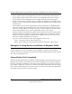
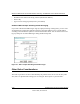
Reference Manual for the ProSafe Wireless 802.11g Firewall/Print Server Model FWG114P These default rules are shown in the Rules table of the Rules menu in Figure 6-2: Figure 6-2: Rules menu You can define additional rules that will specify exceptions to the default rules. By adding custom rules, you can block or allow access based on the service or application, source or destination IP addresses, and time of day.
Reference Manual for the ProSafe Wireless 802.11g Firewall/Print Server Model FWG114P • • • • • Service. From this list, select the application or service to be allowed or blocked. The list already displays many common services, but you are not limited to these choices. Use the Services menu to add any additional services or applications that do not already appear. Action. Choose how you would like this type of traffic to be handled.
Reference Manual for the ProSafe Wireless 802.11g Firewall/Print Server Model FWG114P Note: Some home broadband accounts do not allow you to run any server processes (such as a Web or FTP server). Your ISP may check for servers and suspend your account if it discovers active servers at your location. If you are unsure, refer to the Acceptable Use Policy of your ISP.
Reference Manual for the ProSafe Wireless 802.11g Firewall/Print Server Model FWG114P This rule is shown in Figure 6-3. Example: Port Forwarding for Videoconferencing If you want to allow incoming videoconferencing to be initiated from a restricted range of outside IP addresses, such as from a branch office, you can create an inbound rule. In the example shown in Figure 6-4, CU-SeeMe is a predefined service and its connections are allowed only from a specified range of external IP addresses.
Reference Manual for the ProSafe Wireless 802.11g Firewall/Print Server Model FWG114P Figure 6-5: Service example: port forwarding for VPN when NAT is Off In the example shown in Figure 6-5, UDP port 500 connections are defined as the IPSec service. Figure 6-6: Inbound rule example: VPN IPSec when NAT is off In the example shown in Figure 6-6, VPN IPSec connections are allowed any internal LAN IP address.
Reference Manual for the ProSafe Wireless 802.
Reference Manual for the ProSafe Wireless 802.11g Firewall/Print Server Model FWG114P Order of Precedence for Rules As you define new rules, they are added to the tables in the Rules menu. For any traffic attempting to pass through the firewall, the packet information is subjected to the rules in the order of the entries in the Rules Table, beginning at the top and proceeding to the default rules at the bottom.
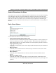
Reference Manual for the ProSafe Wireless 802.11g Firewall/Print Server Model FWG114P Using a Schedule to Block or Allow Content or Traffic If you enabled content filtering in the Block Sites menu, or if you defined an outbound rule to use a schedule, you can set up a schedule for when blocking occurs or when access is restricted. The router allows you to specify when blocking will be enforced by configuring the Schedule tab shown below.
Reference Manual for the ProSafe Wireless 802.11g Firewall/Print Server Model FWG114P Note: Enter the values in 24-hour time format. For example, 10:30 am would be 10 hours and 30 minutes and 10:30 pm would be 22 hours and 30 minutes. Be sure to click Apply when you have finished configuring this menu. Setting the Time Zone The FWG114P Wireless Firewall/Print Server uses the Network Time Protocol (NTP) to obtain the current time and date from one of several Network Time Servers on the Internet.
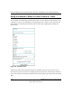
Reference Manual for the ProSafe Wireless 802.11g Firewall/Print Server Model FWG114P Figure 6-9: E-mail menu • Turn e-mail notification on. Select this check box if you want to receive e-mail logs and alerts from the router. • Send alerts and logs by e-mail. If you enable e-mail notification, these boxes cannot be blank. Enter the name or IP address of your ISP’s outgoing (SMTP) mail server (such as mail.myISP.com).
Reference Manual for the ProSafe Wireless 802.11g Firewall/Print Server Model FWG114P • – If a Denial of Service attack is detected. – If a Port Scan is detected. – If a user on your LAN attempts to access a website that you blocked using Keyword blocking. Send logs according to this schedule. You can specify that logs are sent to you according to a schedule. Select whether you would like to receive the logs Hourly, Daily, Weekly, When Full, or None for no logs.
Reference Manual for the ProSafe Wireless 802.11g Firewall/Print Server Model FWG114P Viewing Logs of Web Access or Attempted Web Access The router will log security-related events, such as denied incoming and outgoing service requests, hacker probes, and administrator logins. If you enable content filtering in the Block Sites menu, the Log page will also show you when someone on your network tries to access a blocked site.
Reference Manual for the ProSafe Wireless 802.11g Firewall/Print Server Model FWG114P Log action buttons are described in Table 6-1. Table 6-1. Log action buttons Field Description Refresh Refreshes the log screen. Clear Log Clears the log entries. Send Log E-mails the log immediately. What to Include in the Event Log Use these checkboxes to determine which events are included in the log.
Reference Manual for the ProSafe Wireless 802.11g Firewall/Print Server Model FWG114P Enable one of these three options, as required: • Disable - select this if you do not have a Syslog server. • Broadcast on LAN - the Syslog data is broadcast, rather than sent to a specific Syslog server. Use this if your Syslog Server does not have a fixed IP address.
Chapter 7 Print Server This chapter describes how to install and configure the print server in your ProSafe Wireless 802.11g Firewall/Print Server Model FWG114P. Printing Options The FWG114P supports these methods for printing: • For Windows XP and 2000 Only: TCP/IP Line Printer Remote (LPR) Printing — No software needs to be installed — Windows XP or 2000 users can print directly to the firewall. Print jobs are spooled (queued) on each computer.
Reference Manual for the ProSafe Wireless 802.11g Firewall/Print Server Model FWG114P For Windows XP and 2000, Use TCP/IP LPR Printing Follow these instructions to set up TCP/IP printing on your Windows XP and 2000 PCs. Install the FWG114P, connect your printer to the USB port on the FWG114P, and run the Windows Add Printer Wizard. a. Follow the instructions in the printed Installation Guide or this manual to install your FWG114P. Connect your printer to the USB port on the back of the FWG114P. b.
Reference Manual for the ProSafe Wireless 802.11g Firewall/Print Server Model FWG114P Complete the Add Standard TCP/IP Printer Port Wizard. a. Click Next to proceed with the Add Standard TCP/IP Printer Port Wizard. The Add Port screen will display. b. From the Add Port screen, enter 192.168.0.1, the FWG114P default LAN IP address, in the IP Address field. Note: If you changed the default LAN IP Address of the FWG114P, be sure to use the address you assigned here.
Reference Manual for the ProSafe Wireless 802.11g Firewall/Print Server Model FWG114P Identify the printer connected to FWG114P USB printer port. a. From the Install Printer Software screen selection lists, find the manufacturer and model of the printer you connected to the USB port on the FWG114P. Click Next to proceed. If the printer software is already installed on this computer, the Add Printer Wizard will inform you and let you keep the existing driver. b.
Reference Manual for the ProSafe Wireless 802.11g Firewall/Print Server Model FWG114P For Windows 95/98/Me, Use the Netgear Printer Port Driver Follow these instructions to set up the Netgear Printer Port Drive on Windows 9x PCs. Install the Netgear Printer Port Driver and configuration utility software. a. Follow the instructions in the printed Installation Guide or this manual to install your FWG114P. b. Connect your printer to the USB port on the back of the FWG114P. c.
Reference Manual for the ProSafe Wireless 802.11g Firewall/Print Server Model FWG114P Set up the Netgear printer port driver. a. Click Finish when the Installation Wizard is done. The Printer Port Setup utility displays, and queries the network to locate the print server in the FWG114P. After a short delay, the Printer Port Setup utility will display the port it finds in the FWG114P print server. b.
Reference Manual for the ProSafe Wireless 802.11g Firewall/Print Server Model FWG114P Identify the printer connected to the FWG114P USB printer port. a. From the Add Printer Wizard screen selection lists, find the manufacturer and model of the printer you connected to the USB port on the FWG114P. Click Next to proceed. If the printer software is already installed on this PC, the Add Printer Wizard will inform you and let you keep the existing driver. b.
Reference Manual for the ProSafe Wireless 802.11g Firewall/Print Server Model FWG114P Print a test page to verify successful printing on your network. a. b. Upon completion of the Add Printer Wizard, print a test page. – From the Windows Start menu, select Setup > Printers. – Highlight the printer you just added. – Right-click and the select Properties. The printer properties dialog box opens to the General tab page. – On the General tab page, click Print Test Page.
Reference Manual for the ProSafe Wireless 802.11g Firewall/Print Server Model FWG114P 7. In the Printer Address field, type the name or IP address of the FWG114P Wireless Firewall/ Print Server. The IP address will usually be 192.168.0.1. You can leave the Queue Name blank. Click Verify to make sure your computer can see the printer. You should see the IP address displayed above the button. If no IP Address appears, check that you have correctly typed the queue name or IP Address.
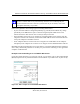
Reference Manual for the ProSafe Wireless 802.11g Firewall/Print Server Model FWG114P Figure 7-1: Print Port Configuration menu Items shown on this screen are as follows: • Port If desired, click Browse Device to select a different device. The Select Device Port button supports multi-port models, but the FWG114P Wireless Firewall/Print Server is a single-port print server. The Port Name is shown in the Printer's Properties. • Banner Check this option to print a banner page before each print job.
Reference Manual for the ProSafe Wireless 802.11g Firewall/Print Server Model FWG114P Troubleshooting the Print Server Note: When the TCP/IP LPR configuration is used, if two long files are sent to the printer at once, Windows will pop up a print failure error message. This message can be ignored. The file will print once the printer finishes printing the first file. This does not happen when the Netgear Printer Port driver is used.
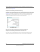
Reference Manual for the ProSafe Wireless 802.11g Firewall/Print Server Model FWG114P c. For Network Path or Queue, enter a dummy value, such as \\123, as shown below. Select NO for “Do you print from MS-DOS-based programs?”. d. Click Next. Figure 7-2: Windows Add Printer Wizard e. The printer wizard will display a message stating that "The Network Printer is off-line". This is OK. Continue the Add Printer Wizard until finished. f. When finished, go to Start -> Settings -> Printers.
Reference Manual for the ProSafe Wireless 802.11g Firewall/Print Server Model FWG114P g. Right-click the new printer and select Properties. Then select the Details tab, as shown below. Figure 7-3: Windows Printer Properties h. Click the Add Port button. On the resulting screen, select Other, then select the NETGEAR Print Server Port as the port to add. i. Click OK to see the Print Port Configuration screen. j. Click the Browse Device button, select the firewall, and click OK.
Reference Manual for the ProSafe Wireless 802.11g Firewall/Print Server Model FWG114P k. Click OK to return to the Printers folders, and right-click on the new printer. Make sure that the Work Offline option is NOT checked. l. From the printer Properties page, General tab, print a test page to confirm that the settings work. m. The new printer icon should no longer be grayed out, and the printer is ready for use.
Chapter 8 Virtual Private Networking This chapter describes how to use the virtual private networking (VPN) features of the FWG114P Wireless Firewall/Print Server. VPN tunnels provide secure, encrypted communications between your local network and a remote network or computer. The FWG114P supports 2 VPN tunnels. Overview of FWG114P Policy-Based VPN Configuration The FWG114P uses state-of-the-art firewall and security technology to facilitate controlled and actively monitored VPN connectivity.
Reference Manual for the ProSafe Wireless 802.11g Firewall/Print Server Model FWG114P Using Policies to Manage VPN Traffic You create policy definitions to manage VPN traffic on the FWG114P. There are two kinds of policies: • IKE Policies: Define the authentication scheme and automatically generate the encryption keys.
Reference Manual for the ProSafe Wireless 802.11g Firewall/Print Server Model FWG114P IKE Policies’ Automatic Key and Authentication Management Click the IKE Policies link from the VPN section of the main menu, and then click the Add button of the IKE Policies screen to display the IKE Policy Configuration menu shown in Figure 8-2.
Reference Manual for the ProSafe Wireless 802.11g Firewall/Print Server Model FWG114P The IKE Policy Configuration fields are defined in the following table. Table 8-1. IKE Policy Configuration Fields Field Description General These settings identify this policy and determine its major characteristics. Policy Name The descriptive name of the IKE policy. Each policy should have a unique policy name. This name is not supplied to the remote VPN endpoint.
Reference Manual for the ProSafe Wireless 802.11g Firewall/Print Server Model FWG114P Table 8-1. IKE Policy Configuration Fields Field Description Remote These parameters apply to the target remote FWG114P, VPN gateway, or VPN client. Remote Identity Type Use this field to identify the remote FWG114P. You can choose one of the following four options from the drop-down list: • By its Internet (WAN) port IP address. • By its Fully Qualified Domain Name (FQDN) — your domain name.
Reference Manual for the ProSafe Wireless 802.11g Firewall/Print Server Model FWG114P VPN Policy Configuration for Auto Key Negotiation An already defined IKE policy is required for VPN - Auto Policy configuration. From the VPN Policies section of the main menu, you can navigate to the VPN - Auto Policy configuration menu.
Reference Manual for the ProSafe Wireless 802.11g Firewall/Print Server Model FWG114P The VPN Auto Policy fields are defined in the following table. Table 8-1. VPN Auto Policy Configuration Fields Field Description General These settings identify this policy and determine its major characteristics. Policy Name The descriptive name of the VPN policy. Each policy should have a unique policy name. This name is not supplied to the remote VPN endpoint. It is only used to help you identify VPN policies.
Reference Manual for the ProSafe Wireless 802.11g Firewall/Print Server Model FWG114P Table 8-1. VPN Auto Policy Configuration Fields Field Description Traffic Selector These settings determine if and when a VPN tunnel will be established. If network traffic meets all criteria, then a VPN tunnel will be created. Local IP The drop-down menu allows you to configure the source IP address of the outbound network traffic for which this VPN policy will provide security.
Reference Manual for the ProSafe Wireless 802.11g Firewall/Print Server Model FWG114P Table 8-1. VPN Auto Policy Configuration Fields Field Description Enable Encryption Encryption Algorithm Enable Authentication Authentication Algorithm NETBIOS Enable Use this checkbox to enable or disable ESP Encryption. If you enable ESP encryption, then select the encryption algorithm: • DES is the default. • 3DES is more secure. Use this checkbox to enable or disable ESP transform for this VPN policy.
Reference Manual for the ProSafe Wireless 802.
Reference Manual for the ProSafe Wireless 802.11g Firewall/Print Server Model FWG114P The VPN Manual Policy fields are defined in the following table. Table 8-1. VPN Manual Policy Configuration Fields Field Description General These settings identify this policy and determine its major characteristics. Policy Name The name of the VPN policy. Each policy should have a unique policy name. This name is not supplied to the remote VPN Endpoint. It is used to help you identify VPN policies.
Reference Manual for the ProSafe Wireless 802.11g Firewall/Print Server Model FWG114P Table 8-1. VPN Manual Policy Configuration Fields Field Description Authenticating Header (AH) Configuration AH specifies the authentication protocol for the VPN header. These settings must match the remote VPN endpoint. Note: The "Incoming" settings here must match the "Outgoing" settings on the remote VPN endpoint, and the "Outgoing" settings here must match the "Incoming" settings on the remote VPN endpoint.
Reference Manual for the ProSafe Wireless 802.11g Firewall/Print Server Model FWG114P Table 8-1. VPN Manual Policy Configuration Fields Field Description SPI - Outgoing Enter a Hex value (3 - 8 chars). Any value is acceptable, provided the remote VPN endpoint has the same value in its "Incoming SPI" field. Enable Encryption Use this checkbox to enable or disable ESP Encryption. Encryption Algorithm If you enable ESP Encryption, then select the Encryption Algorithm: • DES is the default.
Reference Manual for the ProSafe Wireless 802.11g Firewall/Print Server Model FWG114P Table 8-1. VPN Manual Policy Configuration Fields Field Description Key - Out NETBIOS Enable Enter the key in the fields provided. • For MD5, the key should be 16 characters. • For SHA-1, the key should be 20 characters. Any value is acceptable, provided the remote VPN endpoint has the same value in its Authentication Algorithm "Key - In" field.
Reference Manual for the ProSafe Wireless 802.11g Firewall/Print Server Model FWG114P Whenever an IKE policy receives the certificate from a peer, it checks for this certificate in the CRL on the FWG114P obtained from the corresponding CA. If the certificate is not present in the CRL it means that the certificate is not revoked. IKE can then use this certificate for authentication.
Reference Manual for the ProSafe Wireless 802.11g Firewall/Print Server Model FWG114P Follow this procedure to configure a VPN tunnel using the VPN Wizard. Note: The LAN IP address ranges of each VPN endpoint must be different. The connection will fail if both are using the NETGEAR default address range of 192.168.0.x. 1. Log in to the FVS318 on LAN A at its default LAN address of http://192.168.0.1 with its default user name of admin and password of password.
Reference Manual for the ProSafe Wireless 802.11g Firewall/Print Server Model FWG114P 3. Fill in the IP Address or FQDN for the target VPN endpoint WAN connection and click Next. Figure 8-7: Remote IP 4. Identify the IP addresses at the target endpoint which can use this tunnel, and click Next. Figure 8-8: Secure Connection Remote Accessibility The Summary screen below displays.
Reference Manual for the ProSafe Wireless 802.11g Firewall/Print Server Model FWG114P Figure 8-9: VPN Wizard Summary To view the VPNC recommended authentication and encryption Phase 1 and Phase 2 settings the VPN Wizard used, click the “here” link. 5. Click Done to complete the configuration procedure. The VPN Settings menu displays showing that the new tunnel is enabled To view or modify the tunnel settings, select the radio button next to the tunnel entry and click Edit.
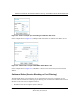
Reference Manual for the ProSafe Wireless 802.11g Firewall/Print Server Model FWG114P VPNC Scenario 1: Gateway to Gateway with Preshared Secrets The following is a typical gateway-to-gateway VPN that uses a preshared secret for authentication. 10.5.6.0/24 172.23.9.0/24 Gateway A 10.5.6.1 Gateway B Internet 14.15.16.17 22.23.24.25 172.23.9.1 Figure 8-10: VPN Consortium Scenario 1 Gateway A connects the internal LAN 10.5.6.0/24 to the Internet. Gateway A's LAN interface has the address 10.5.6.
Reference Manual for the ProSafe Wireless 802.11g Firewall/Print Server Model FWG114P Scenario 1: FWG114P to FWG114P with Preshared Secrets Note: This scenario assumes all ports are open on the FWG114P. You can verify this by reviewing the security settings as seen in the “Rules menu” on page 6-5. 6FHQDULR *DWHZD\ % *DWHZD\ $ /$1 ,3 Á?aM?a +Á.?wjËoåÔ±¤¤~Ë8ÁjjÄÄË ÁjÝ?Ê+ÁÍË.jÁÜjÁ $&7 $&7 7(67 $/(57 02).4%2 $/(57 -/$%- /1. $&7 ).4%2.
Reference Manual for the ProSafe Wireless 802.11g Firewall/Print Server Model FWG114P c. From the main menu Advanced section, click on the LAN IP Setup link. Figure 8-13: LAN IP configuration menu d. Configure the LAN IP address according to the settings above and click Apply to save your settings. For more information on LAN TCP/IP setup topics, please see “Using the LAN IP Setup Options” on page 10-5.
Reference Manual for the ProSafe Wireless 802.11g Firewall/Print Server Model FWG114P 3. Set up the IKE Policy illustrated below on the FWG114P. a. From the main menu VPN section, click on the IKE Policies link, and then click the Add button to display the screen below. Figure 8-14: Scenario 1 IKE Policy b. Configure the IKE Policy according to the settings in the illustration above and click Apply to save your settings.
Reference Manual for the ProSafe Wireless 802.11g Firewall/Print Server Model FWG114P 4. Set up the FWG114P VPN -Auto Policy illustrated below. a. From the main menu VPN section, click on the VPN Policies link, and then click on the Add Auto Policy button. WAN IP address LAN IP addresses Figure 8-15: Scenario 1 VPN - Auto Policy b. Configure the IKE Policy according to the settings in the illustration above and click Apply to save your settings.
Reference Manual for the ProSafe Wireless 802.11g Firewall/Print Server Model FWG114P How to Check VPN Connections You can test connectivity and view VPN status information on the FWG114P. 1. 2. To test connectivity between the Gateway A FWG114P LAN and the Gateway B LAN, follow these steps: a. Using our example, from a PC attached to the FWG114P on LAN A, on a Windows PC click the Start button on the taskbar and then click Run. b. Enter ping -t 172.23.9.1, and then click OK. c.
Reference Manual for the ProSafe Wireless 802.11g Firewall/Print Server Model FWG114P VPNC Scenario 2: Gateway-to-Gateway with Certificates The following is a typical gateway-to-gateway VPN that uses PKIX certificates for authentication. 10.5.6.0/24 172.23.9.0/24 Gateway A 10.5.6.1 Gateway B Internet 14.15.16.17 22.23.24.25 172.23.9.1 Figure 8-16: VPN Consortium Scenario 2 Gateway A connects the internal LAN 10.5.6.0/24 to the Internet. Gateway A's LAN interface has the address 10.5.6.
Reference Manual for the ProSafe Wireless 802.11g Firewall/Print Server Model FWG114P • Selectors for all IP protocols, all ports, between 10.5.6.0/24 and 172.23.9.0/24, using IPv4 subnets Scenario 2: FWG114P to FWG114P with Certificates The following is a typical gateway-to-gateway VPN that uses Public Key Infrastructure x.509 (PKIX) certificates for authentication. The network setup is identical to the one given in scenario 1.
Reference Manual for the ProSafe Wireless 802.11g Firewall/Print Server Model FWG114P b. Click the Generate Request button to display the screen illustrated in Figure 8-17 below. . FWG114P Figure 8-17: Generate Self Certificate Request menu c. Fill in the fields on the Add Self Certificate screen. • Required – – – – – • Name. Enter a name to identify this certificate. Subject. This is the name which other organizations will see as the holder (owner) of this certificate.
Reference Manual for the ProSafe Wireless 802.11g Firewall/Print Server Model FWG114P – d. E-mail Address. You can enter your e-mail address here. Click the Next button to continue. The FWG114P generates a Self Certificate Request as shown below. Highlight, copy and paste this data into a text file. Figure 8-18: Self Certificate Request data 4. Transmit the Self Certificate Request data to the Trusted Root CA. a.
Reference Manual for the ProSafe Wireless 802.11g Firewall/Print Server Model FWG114P c. When you have finished gathering the Self Certificate Request data, click the Done button. You will return to the Certificates screen where your pending “FWG114P” Self Certificate Request will be listed, as illustrated in Figure 8-19 below. FWG114P Figure 8-19: Self Certificate Requests table 5. Receive the certificate back from the Trusted Root CA and save it as a text file.
Reference Manual for the ProSafe Wireless 802.11g Firewall/Print Server Model FWG114P f. You will now see the “FWG114P” entry in the Active Self Certificates table and the pending “FWG114P” Self Certificate Request is gone, as illustrated below. FWG1 Figure 8-20: Self Certificates table 7. Associate the new certificate and the Trusted Root CA certificate on the FWG114P. a.
Reference Manual for the ProSafe Wireless 802.11g Firewall/Print Server Model FWG114P Now, the traffic from devices within the range of the LAN subnet addresses on FWG114P A and Gateway B will be authenticated using the certificates rather than via a shared key. 8. Set up Certificate Revocation List (CRL) checking. a. Get a copy of the CRL from the CA and save it as a text file.
Reference Manual for the ProSafe Wireless 802.11g Firewall/Print Server Model FWG114P Netgear VPN Client to FWG114P Follow these procedures to configure a VPN tunnel from a NETGEAR ProSafe VPN Client to an FWG114P. This case study follows the Virtual Private Network Consortium (VPNC) interoperability profile guidelines. The menu options for the FVS328, FVL328, FWAG114, and FWG114P are the same.
Reference Manual for the ProSafe Wireless 802.11g Firewall/Print Server Model FWG114P 1HWZRUN $GGUHVVHV *DWHZD\ :$1 ,3 /$1 ,3 Á?aM?a +Á.?wjËoåÔ±¤¤~Ë8ÁjjÄÄË ÁjÝ?Ê+ÁÍË.jÁÜjÁ $&7 $&7 7(67 $/(57 02).4%2 $/(57 -/$%- # 8 ¤¤|+ 3:5 &OLHQW :$1 ,3 /1. $&7 /1. $&7 ).4%2.%4 ,/#!, 7,!.
Reference Manual for the ProSafe Wireless 802.11g Firewall/Print Server Model FWG114P 2. Click IKE Policies under the VPN menu and click Add on the IKE Policies Menu. Figure 8-23: NETGEAR FWG114P IKE Policy Configuration – – – – – Enter a descriptive name for the policy in the Policy Name field. This name is not supplied to the remote VPN endpoint. It is used to help you manage the IKE policies. In our example, we used VPNclient as the Policy Name.
Reference Manual for the ProSafe Wireless 802.11g Firewall/Print Server Model FWG114P – From the Remote Identity drop-down box, select Fully Qualified Domain Name. – Type VPNclient in the Remote Identity Data. This will also be entered in the VPN Client My Identity ID Type fields, as seen in “My Identity” on page 8-40. – From the Encryption Algorithm drop-down box, select 3DES.
Reference Manual for the ProSafe Wireless 802.11g Firewall/Print Server Model FWG114P 3. Click the VPN Policies link under the VPN category on the left side of the main menu. This will take you to the VPN Policies Menu page. Click Add Auto Policy. This will open a new screen titled VPN – Auto Policy. Figure 8-24: VPN – Auto Policy settings – – Enter a unique name to identify this policy. This name is not supplied to the remote VPN endpoint. In our example, we use VPNclient as the Policy Name.
Reference Manual for the ProSafe Wireless 802.11g Firewall/Print Server Model FWG114P – – – – – – – – – – – – – From the Remote VPN Endpoint Address Type drop-down box, select IP Address. Type 0.0.0.0 as the Address Data of the client because we are assuming the remote PC will have a dynamically assigned IP address. This will also be entered in the VPN Client Internal Network IP Address field, as seen in “My Identity” on page 8-40. Type 86400 in the SA Life Time (Seconds) field.
Reference Manual for the ProSafe Wireless 802.11g Firewall/Print Server Model FWG114P – – – Select Enable Authentication in the ESP Configuration Enable Authentication check box. Note: Do not confuse this with the Authentication Protocol (AH) option. Using the AH option will prevent clients behind a home NAT router from connecting. From the ESP Configuration Authentication Algorithm drop-down box, select SHA-1.
Reference Manual for the ProSafe Wireless 802.11g Firewall/Print Server Model FWG114P 1. Install the Netgear VPN Client Software on the PC. Note: Before installing the Netgear VPN Client software, be sure to turn off any virus protection or firewall software you may be running on your PC. 2. • You may need to insert your Windows CD to complete the installation. • Reboot your PC after installing the client software. Configure the Connection Network Settings.
Reference Manual for the ProSafe Wireless 802.11g Firewall/Print Server Model FWG114P Note: If the configuration settings on this screen are not available for editing, go to the Options menu, select Secure, and Specified Options to enable editing these settings. From the Edit menu of the Security Policy Editor, click Add, then Connection. A “New Connection” listing appears. Rename the “New Connection” to FWG114P. b. Ensure that the following settings are configured: – – – 3.