User Manual 8-Port Gigabit Ethernet Plus Switch with 2-Port 10G/Multi-Gig Uplinks Model GS110EMX November 2021 202-11810-05 NETGEAR, Inc. 350 E.
8-Port Gigabit Ethernet Plus Switch with 2-Port 10G/Multi-Gig Uplinks GS110EMX Support and Community Visit netgear.com/support to get your questions answered and access the latest downloads. You can also check out our NETGEAR Community for helpful advice at community.netgear.com. Regulatory and Legal Si ce produit est vendu au Canada, vous pouvez accéder à ce document en français canadien à https://www.netgear.com/support/download/.
8-Port Gigabit Ethernet Plus Switch with 2-Port 10G/Multi-Gig Uplinks GS110EMX (Continued) Publication Part Number Publish Date Comments 202-11810-02 November 2017 Added information about accessing a switch from a Mac using a Firefox plug-in. 202-11810-01 November 2017 First publication.
Contents Chapter 1 Hardware Overview of the Switch Related documentation.......................................................................8 Switch package contents.....................................................................8 Front panel............................................................................................9 Status LEDs..........................................................................................10 Back panel.....................................................
8-Port Gigabit Ethernet Plus Switch with 2-Port 10G/Multi-Gig Uplinks GS110EMX Chapter 4 Optimize Performance With Quality of Service Enable 802.1p/DSCP-based quality of service...............................40 Configure port-based quality of service..........................................40 Set up rate limiting.............................................................................42 Set up broadcast filtering..................................................................
8-Port Gigabit Ethernet Plus Switch with 2-Port 10G/Multi-Gig Uplinks GS110EMX Appendix A Factory Default Settings and Technical Specifications Factory default settings......................................................................73 Basic technical specifications............................................................74 Appendix B Mount the Switch Attach the switch to a wall.................................................................77 Install the switch in a rack..........................
1 Hardware Overview of the Switch The NETGEAR 8-Port Gigabit Ethernet Plus Switch with 2-Port 10G/Multi-Gig Uplinks Model GS110EMX, in this manual referred to as the switch, is intended for small and medium-sized business networks and home offices that require high-speed uplinks. In addition to the eight Gigabit Ethernet ports, the switch provides two uplink 10-Gigabit/Multi-Gigabit (5-speed) ports that provide either 100 Mbps, 1 Gbps, 2.5 Gbps, 5 Gbps or 10 Gbps connectivity.
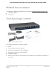
-Port Gigabit Ethernet Plus Switch with 2-Port 10G/Multi-Gig Uplinks GS110EMX Related documentation The following related documentation is available at downloadcenter.netgear.com: • Installation guide • Data sheet Switch package contents Figure 1.
8-Port Gigabit Ethernet Plus Switch with 2-Port 10G/Multi-Gig Uplinks GS110EMX Front panel Figure 2. Front panel The following table lists the front panel components from left to right. Table 1.
8-Port Gigabit Ethernet Plus Switch with 2-Port 10G/Multi-Gig Uplinks GS110EMX Status LEDs Status LEDs are located on the front panel of the switch. Each port provides a left LED and a right LED that, in combination, indicate speed and activity. Table 2. LED descriptions LED Left LED Power LED N/A (single LED only) Off. No power is supplied to the switch. Solid green. Power is supplied to the switch and the switch is ready for operation.
8-Port Gigabit Ethernet Plus Switch with 2-Port 10G/Multi-Gig Uplinks GS110EMX Back panel Figure 3. Back panel The back panel of the switch provides a Kensington lock slot for an optional lock and the 12V, 12.5A DC connector for the power adapter. Switch label The switch label on the bottom panel of the switch shows the serial number, MAC address, default login information, and other information for the switch. Figure 4.
8-Port Gigabit Ethernet Plus Switch with 2-Port 10G/Multi-Gig Uplinks GS110EMX To reduce the risk of bodily injury, electrical shock, fire, and damage to the equipment, observe the following precautions: • This product is designed for indoor use only in a temperature-controlled and humidity-controlled environment. Note the following: - For more information about the environment in which this product must operate, see the environmental specifications in the appendix or the data sheet.
8-Port Gigabit Ethernet Plus Switch with 2-Port 10G/Multi-Gig Uplinks GS110EMX • Do not spill food or liquids on your product components, and never operate the product in a wet environment. If the product gets wet, see the appropriate section in your troubleshooting guide, or contact your trained service provider. • Do not push any objects into the openings of your product. Doing so can cause fire or electric shock by shorting out interior components. • Use the product only with approved equipment.
8-Port Gigabit Ethernet Plus Switch with 2-Port 10G/Multi-Gig Uplinks GS110EMX • If applicable to your product, the peripheral power cables are equipped with three-prong plugs to help ensure proper grounding. Do not use adapter plugs or remove the grounding prong from a cable. If you must use an extension cable, use a three-wire cable with properly grounded plugs. • Observe extension cable and power strip ratings.
2 Install and Access the Switch in Your Network This chapter describes how you can install and access the switch in your network.
8-Port Gigabit Ethernet Plus Switch with 2-Port 10G/Multi-Gig Uplinks GS110EMX Set up the switch in your network and power on the switch Before you set up the switch in your network, we recommend that you review the information in the following table, which describes the network cables that you can use for the switch connections and the speeds that these cables can support, up to 100 meters (328 feet). Table 3. Cables and speeds Speed Cable Type 100 Mbps Category 5 (Cat 5) or higher rated 1 Gbps, 2.
8-Port Gigabit Ethernet Plus Switch with 2-Port 10G/Multi-Gig Uplinks GS110EMX Table 4. Figure components Letter Description Letter Description A GS110EMX switch E Computer B 10G aggregation switch F WiFi access point C Network router G 10G NAS device D Internet Note: Red lines indicate 10G connections. Black lines indicate 1G connections. To set up the switch in your network and power on the switch: 1. Connect devices to the RJ-45 network ports on the front panel of the switch (A).
8-Port Gigabit Ethernet Plus Switch with 2-Port 10G/Multi-Gig Uplinks GS110EMX Access the switch and discover the IP address of the switch By default, the switch receives an IP address from a DHCP server (or a router that functions as a DHCP server) in your network. For information about setting up a fixed (static) IP address on the switch, see Set up a fixed IP address for the switch on page 21.
8-Port Gigabit Ethernet Plus Switch with 2-Port 10G/Multi-Gig Uplinks GS110EMX Access the switch from a Mac using Bonjour If your Mac supports Bonjour, you can use the following procedure. If your Mac does not support Bonjour, see Access the switch from a Mac or Windows-based computer using the NETGEAR Switch Discovery Tool on page 20. To access the switch from a Mac using Bonjour and discover the switch IP address: 1. Open the Safari browser. 2. Select Safari > Preferences. The General page displays. 3.
8-Port Gigabit Ethernet Plus Switch with 2-Port 10G/Multi-Gig Uplinks GS110EMX Access the switch from a Mac or Windows-based computer using the NETGEAR Switch Discovery Tool The NETGEAR Switch Discovery Tool lets you discover the switch in your network and access the local browser interface of the switch from a Mac or a 64-bit Windows-based computer. If your Mac does not support Bonjour, use the following procedure.
8-Port Gigabit Ethernet Plus Switch with 2-Port 10G/Multi-Gig Uplinks GS110EMX For each switch, the tool displays the IP address. 10. To access the local browser interface of the switch, click the ADMIN PAGE button. The login page of the local browser interface opens. 11. Enter the switch password. The default password is password. The password is case-sensitive. The Switch Information page displays. The page shows the IP address that is assigned to the switch.
8-Port Gigabit Ethernet Plus Switch with 2-Port 10G/Multi-Gig Uplinks GS110EMX Set up a fixed IP address for the switch through a network connection If the switch and your computer are connected to the same network (which is the most the likely situation), you can change the IP address of the switch through a network connection. To disable the DHCP client of the switch and change the IP address of the switch to a fixed IP address by using a network connection: 1.
8-Port Gigabit Ethernet Plus Switch with 2-Port 10G/Multi-Gig Uplinks GS110EMX Set up a fixed IP address for the switch by connecting directly to the switch off-network In the unlikely situation that the switch is not connected to a network, or for some reason you cannot connect to the switch over a network connection, you can change the IP address of the switch by using an Ethernet cable and making a direct connection to the switch.
8-Port Gigabit Ethernet Plus Switch with 2-Port 10G/Multi-Gig Uplinks GS110EMX For more information, see Set up the switch in your network and power on the switch on page 16. 11. Restore your computer to its original IP address. 12. Verify that you can connect to the switch with its new IP address: a. Connect your computer to the same network as the switch. You can use a WiFi or wired network connection. b. Launch a web browser. c.
8-Port Gigabit Ethernet Plus Switch with 2-Port 10G/Multi-Gig Uplinks GS110EMX 7. Type the new password in the New Password field and in the Re-type New Password field. 8. Click the Apply button. Your settings are saved. Keep the new password in a secure location so that you can access the switch in the future. Register your product Registering your product allows you to receive email alerts and streamlines the technical support process.
3 Use VLANS for Traffic Segmentation This chapter describes how you can use VLANs to segment traffic on the switch. The chapter contains the following sections: • • • • • • • • VLAN overview Create basic port-based VLANs Assign ports to multiple port-based VLANs Create 802.1Q-based VLANs in a basic configuration Create 802.1Q-based VLANs in an advanced configuration Add tagged or untagged ports to an 802.1Q-based VLAN Specify a port PVID for an 802.
8-Port Gigabit Ethernet Plus Switch with 2-Port 10G/Multi-Gig Uplinks GS110EMX VLAN overview Virtual LANs (VLANs) are made up of networked devices that are grouped logically into separate networks. You can group ports on a switch to create a virtual network made up of the devices connected to the ports. Ports can be grouped in VLANs using port-based or 802.1Q criteria: • Port-based VLANs. Assign ports to virtual networks. Ports with the same VLAN ID are placed in the same VLAN.
8-Port Gigabit Ethernet Plus Switch with 2-Port 10G/Multi-Gig Uplinks GS110EMX 5. Select VLAN. The Basic Port-based VLAN Status page displays. 6. If this is the first time that you are accessing this page or if you are changing the VLAN assignment method, select the Enable radio button and continue with Step 7. Otherwise, see Step 9. A pop-up window opens, informing you that the current VLAN settings will be lost. 7. Click the OK button. The pop-up window closes. 8. Click the Apply button.
8-Port Gigabit Ethernet Plus Switch with 2-Port 10G/Multi-Gig Uplinks GS110EMX 3. In the address field of your web browser, enter the IP address of the switch. The login page displays. 4. Enter the switch password. The default password is password. The password is case-sensitive. The Switch Information page displays. 5. Select VLAN. The Basic Port-based VLAN Status page displays. 6.
8-Port Gigabit Ethernet Plus Switch with 2-Port 10G/Multi-Gig Uplinks GS110EMX Create 802.1Q-based VLANs in a basic configuration A 802.1Q-based VLAN configuration lets you assign ports on the switch to a VLAN with an ID number in the range of 1–4093. By default, all ports are members of VLAN 1. In an advanced 802.1Q-based VLAN configuration, you can set up VLANs to which you can add tagged or untagged ports and you can use port VLAN ID (PVID). For more information, Create 802.
8-Port Gigabit Ethernet Plus Switch with 2-Port 10G/Multi-Gig Uplinks GS110EMX You can enter a VLAN ID from 1 to 4093. If all the VLANs share an uplink to the Internet or servers, enter all in the VLAN ID field for the port that you want to use for the uplink. Note: If ports are members of the same LAG, you must assign them to the same VLAN. 10. Click the Apply button. Your settings are saved. Create 802.1Q-based VLANs in an advanced configuration In an advanced 802.
8-Port Gigabit Ethernet Plus Switch with 2-Port 10G/Multi-Gig Uplinks GS110EMX 7. Click the OK button. The pop-up window closes. 8. Click the Apply button. Your settings are saved. The VLAN Identifier Setting table displays. 9. In the VLAN ID field, enter a VLAN ID. You can enter a VLAN ID from 1 to 4093. 10. Click the Add button. The new VLAN is added to the VLAN Identifier Setting table. After you create a new VLAN ID, use the VLAN membership option to add ports to the VLAN. (Select VLAN > 802.
8-Port Gigabit Ethernet Plus Switch with 2-Port 10G/Multi-Gig Uplinks GS110EMX The login page displays. 4. Enter the switch password. The default password is password. The password is case-sensitive. The Switch Information page displays. 5. Select VLAN > 802.1Q > Advanced > VLAN Configuration. The Advanced 802.1Q VLAN Status page displays. The menu on the left displays more options. 6. Select VLAN Membership. You can select VLAN Membership only if you already enabled the advanced 802.
8-Port Gigabit Ethernet Plus Switch with 2-Port 10G/Multi-Gig Uplinks GS110EMX Specify a port PVID for an 802.1Q-based VLAN A default port VLAN ID (PVID) is a VLAN ID tag that the switch assigns to data packets it receives that are not already addressed (tagged) for a particular VLAN. For example, if you connected a computer on port 6 and you want it to be a part of VLAN 2, configure port 6 to automatically add a PVID of 2 to all data received from the computer.
8-Port Gigabit Ethernet Plus Switch with 2-Port 10G/Multi-Gig Uplinks GS110EMX Manage the voice VLAN The switch supports a voice VLAN to facilitate voice over IP (VoIP) traffic. You can configure the voice VLAN only if you enable the 802.1Q VLAN mode (see Create 802.1Q-based VLANs in a basic configuration on page 30 or Create 802.1Q-based VLANs in an advanced configuration on page 31).
8-Port Gigabit Ethernet Plus Switch with 2-Port 10G/Multi-Gig Uplinks GS110EMX You can select either the default VLAN ID (1) or a VLAN ID that you manually added (see Create 802.1Q-based VLANs in a basic configuration on page 30 or Create 802.1Q-based VLANs in an advanced configuration on page 31). 7. In the Class of Service menu, select the class value for the voice VLAN. You can select a value from 0 (the lowest priority) to 7 (the highest priority). The default CoS value is 6. 8. Click the Apply button.
8-Port Gigabit Ethernet Plus Switch with 2-Port 10G/Multi-Gig Uplinks GS110EMX Manage the OUI table The switch includes default Organizationally Unique Identifiers (OUIs), which are associated with VoIP phones of specific manufacturers. All traffic received on voice VLAN ports from VoIP phones with a listed OUI is forwarded on the voice VLAN. You can add and remove OUIs. The maximum number of OUI entries in the table is 15.
8-Port Gigabit Ethernet Plus Switch with 2-Port 10G/Multi-Gig Uplinks GS110EMX • To change an existing OUI prefix in the table, do the following: a. Select the OUI. b. Change the OUI in the Telephony (OUIs) field, change the description in the Description field, or change both. c. Click the Apply button. Your settings are saved.
4 Optimize Performance With Quality of Service This chapter covers the following topics: • • • • Enable 802.
8-Port Gigabit Ethernet Plus Switch with 2-Port 10G/Multi-Gig Uplinks GS110EMX Enable 802.1p/DSCP-based quality of service 802.1p/DSCP-based priority uses a field in the data packet header that identifies the class of data in the packet (for example, voice or video). When 802.1p/DSCP-based priority is used, the switch reads information in the packet header to determine the priority to assign to the packet. The switch reads both 802.1p tag information and DSCP/ToS tag information.
8-Port Gigabit Ethernet Plus Switch with 2-Port 10G/Multi-Gig Uplinks GS110EMX configured as higher priority transmit their packets first. You must determine which ports will carry delay-sensitive data. To configure port-based QoS: 1. Connect your computer to the same network as the switch. You can use a WiFi or wired network connection, or connect directly to a switch that is off-network using an Ethernet cable. 2. Launch a web browser. 3.
8-Port Gigabit Ethernet Plus Switch with 2-Port 10G/Multi-Gig Uplinks GS110EMX Set up rate limiting You can limit the rate at which the switch accepts incoming data and the rate that it retransmits outgoing data. Rate limiting can be set for a port in addition to other QoS settings. If the port rate limit is set, the switch restricts the acceptance or retransmission of data to the values configured. To set up rate limiting: 1. Connect your computer to the same network as the switch.
8-Port Gigabit Ethernet Plus Switch with 2-Port 10G/Multi-Gig Uplinks GS110EMX broadcast storms can delay or halt the transmission of other data. Some switches allow you to select a storm control rate for each port. Others assign a predetermined storm control rate for all ports on the switch. If broadcast traffic on any port exceeds the threshold that you set, the switch temporarily blocks (discards) the broadcast packets. To set up broadcast filtering: 1.
5 Manage Network Settings This chapter contains the following sections: • • • • • Specify IP address settings for the switch Use the local browser interface to specify the switch IP address Manage switch discovery protocols Manage multicast traffic with IGMP snooping Set up link aggregation 44
8-Port Gigabit Ethernet Plus Switch with 2-Port 10G/Multi-Gig Uplinks GS110EMX Specify IP address settings for the switch By default, the switch IP address works as follows: • If you cable the switch to a network with a DHCP server before you power on the switch, the DHCP server assigns an IP address to the switch when the switch is powered on. • If you power on the switch when it is not connected to a network with a DHCP server, the switch uses its default IP address, which is 192.168.0.239.
8-Port Gigabit Ethernet Plus Switch with 2-Port 10G/Multi-Gig Uplinks GS110EMX Manage switch discovery protocols It is important to know the IP address of the switch so that you can access the local browser interface of the switch. The switch supports Universal Plug and Play (UPnP), Bonjour, and NETGEAR Switch Discovery Protocol (NSDP), which are protocols that can discover the switch.
8-Port Gigabit Ethernet Plus Switch with 2-Port 10G/Multi-Gig Uplinks GS110EMX Manage Bonjour A Mac OS device that supports Bonjour can discover the switch in the network so that you can find the switch IP address and log in to the local browser interface of the switch. Bonjour is enabled by default. You can disable Bonjour for security reasons. Note: On a Mac OS device that does not support Bonjour, use the Mozilla Firefox browser with the Ciaociao plug-in to discover the switch in the network.
8-Port Gigabit Ethernet Plus Switch with 2-Port 10G/Multi-Gig Uplinks GS110EMX To manage NSDP: 1. Connect your computer to the same network as the switch. You can use a WiFi or wired network connection, or connect directly to a switch that is off-network using an Ethernet cable. 2. Launch a web browser. 3. In the address field of your web browser, enter the IP address of the switch. The login page displays. 4. Enter the switch password. The default password is password. The password is case-sensitive.
8-Port Gigabit Ethernet Plus Switch with 2-Port 10G/Multi-Gig Uplinks GS110EMX Customize IGMP snooping By default, IGMP snooping is enabled. You can customize the settings for your network. To customize IGMP snooping: 1. Connect your computer to the same network as the switch. You can use a WiFi or wired network connection, or connect directly to a switch that is off-network using an Ethernet cable. 2. Launch a web browser. 3. In the address field of your web browser, enter the IP address of the switch.
8-Port Gigabit Ethernet Plus Switch with 2-Port 10G/Multi-Gig Uplinks GS110EMX 10. (Optional) Select an option from the IGMP Snooping Static Router Port menu. You can select a port to be the dedicated IGMP snooping static router port if no IGMP query exists in the network for the switch to discover the router port dynamically. After a port is selected as the static router port, all IGMP Join and Leave reports are forwarded to the port. 11. Click the Apply button. Your settings are saved.
8-Port Gigabit Ethernet Plus Switch with 2-Port 10G/Multi-Gig Uplinks GS110EMX Your settings are saved. Set up link aggregation Link aggregation groups (LAGs) allow you to combine multiple Ethernet links into a single logical link. Network devices treat the aggregation as if it were a single link, which increases fault tolerance and load sharing. Configure LAG membership before you enable the LAG.
8-Port Gigabit Ethernet Plus Switch with 2-Port 10G/Multi-Gig Uplinks GS110EMX The default password is password. The password is case-sensitive. The Switch Information page displays. 5. Select System > LAG > LAG Membership. The LAG Membership page displays. 6. In the LAG ID menu, select the LAG ID. You can select a LAG ID from 1 to 5. 7. Enter a name in the LAG Name field. You can enter a name of up to 15 printable ASCII characters, including a blank space and special characters such as !, @, #, and $. 8.
8-Port Gigabit Ethernet Plus Switch with 2-Port 10G/Multi-Gig Uplinks GS110EMX To specify an LACP group: 1. Connect your computer to the same network as the switch. You can use a WiFi or wired network connection, or connect directly to a switch that is off-network using an Ethernet cable. 2. Launch a web browser. 3. In the address field of your web browser, enter the IP address of the switch. The login page displays. 4. Enter the switch password. The default password is password.
8-Port Gigabit Ethernet Plus Switch with 2-Port 10G/Multi-Gig Uplinks GS110EMX Your settings are saved. Set up the LACP system priority for the switch The LACP system priority specifies the link aggregation priority of the switch relative to the devices at the other ends of the links on which link aggregation is enabled. The default is 32768. A higher value indicates a lower priority. The value of the priority applies to all LACP LAGs that you set up on the switch. To change the LACP system priority: 1.
8-Port Gigabit Ethernet Plus Switch with 2-Port 10G/Multi-Gig Uplinks GS110EMX 3. In the address field of your web browser, enter the IP address of the switch. The login page displays. 4. Enter the switch password. The default password is password. The password is case-sensitive. The Switch Information page displays. 5. Select System > LAG > LACP Port Configuration. The LACP Port Configuration page displays. 6. Select one or more ports. 7. In the LACP Priority field, enter a new value.
6 Manage and Monitor the Switch This chapter covers the following topics: • • • • • • • • • • • • Manage flow control Manage the port speed and the port status Enable loop prevention Manage the power saving mode Manually download and upgrade the firmware Reboot the switch Save the switch configuration Restore a saved switch configuration Return the switch to its factory default settings Enable port mirroring View switch information or change the switch device name View or clear the port statistics 56
8-Port Gigabit Ethernet Plus Switch with 2-Port 10G/Multi-Gig Uplinks GS110EMX Manage flow control Flow control works by pausing a port if the port becomes oversubscribed. It drops all traffic for small intervals of time during the congestion condition. You can enable or disable IEEE 802.3x flow control. By default, flow control is disabled. To manage flow control: 1. Connect your computer to the same network as the switch.
8-Port Gigabit Ethernet Plus Switch with 2-Port 10G/Multi-Gig Uplinks GS110EMX To manage the port speed and the port status and add a port description: 1. Connect your computer to the same network as the switch. You can use a WiFi or wired network connection, or connect directly to a switch that is off-network using an Ethernet cable. 2. Launch a web browser. 3. In the address field of your web browser, enter the IP address of the switch. The login page displays. 4. Enter the switch password.
8-Port Gigabit Ethernet Plus Switch with 2-Port 10G/Multi-Gig Uplinks GS110EMX Enable loop prevention If loop prevention is enabled and the switch detects a loop, the switch blocks one of the ports that are part of the loop and both LEDs of that port blink at a constant speed. If two ports are part of a loop, the port with the highest port number is blocked. For example, if port 1 and port 2 are part of a loop, port 2 is blocked while port 1 continues to process traffic.
8-Port Gigabit Ethernet Plus Switch with 2-Port 10G/Multi-Gig Uplinks GS110EMX To manage the power saving mode: 1. Connect your computer to the same network as the switch. You can use a WiFi or wired network connection, or connect directly to a switch that is off-network using an Ethernet cable. 2. Launch a web browser. 3. In the address field of your web browser, enter the IP address of the switch. The login page displays. 4. Enter the switch password. The default password is password.
8-Port Gigabit Ethernet Plus Switch with 2-Port 10G/Multi-Gig Uplinks GS110EMX You can use a WiFi or wired network connection, or connect directly to a switch that is off-network using an Ethernet cable. 6. Launch a web browser. 7. In the address field of your web browser, enter the IP address of the switch. The login page displays. 8. Enter the switch password. The default password is password. The password is case-sensitive. The Switch Information page displays. 9.
8-Port Gigabit Ethernet Plus Switch with 2-Port 10G/Multi-Gig Uplinks GS110EMX 5. Select System > Maintenance > Device Reboot. The Device Reboot page displays. 6. Select the check box. 7. Click the Apply button. The switch reboots. Save the switch configuration You can save the switch configuration as a file. We recommend that you save the configuration. Then you can quickly restore the switch configuration if you change the settings and then decide to return the switch to its previous settings.
8-Port Gigabit Ethernet Plus Switch with 2-Port 10G/Multi-Gig Uplinks GS110EMX Restore a saved switch configuration You can restore a switch configuration that you saved. To restore the switch configuration that you saved: 1. Connect your computer to the same network as the switch. You can use a WiFi or wired network connection, or connect directly to a switch that is off-network using an Ethernet cable. 2. Launch a web browser. 3.
8-Port Gigabit Ethernet Plus Switch with 2-Port 10G/Multi-Gig Uplinks GS110EMX Use the Factory Defaults button to reset the switch You can use the Factory Defaults button to reset the switch to its factory default settings. CAUTION: This process erases all settings that you configured on the switch. To reset the switch to factory default settings using the Factory Defaults button: 1. On the front panel of the switch, locate the recessed Factory Defaults button. 2.
8-Port Gigabit Ethernet Plus Switch with 2-Port 10G/Multi-Gig Uplinks GS110EMX 6. Select the check box. 7. Click the Apply button. The switch returns to its factory default settings. The switch restarts to load the restored configuration. WARNING: Do not interrupt the network connection or power to the switch during the reset process. Do not disconnect any Ethernet cables or power off the switch until the reset and restart process is complete.
8-Port Gigabit Ethernet Plus Switch with 2-Port 10G/Multi-Gig Uplinks GS110EMX By default, mirroring is disabled. 9. Click the Apply button. Your settings are saved. View switch information or change the switch device name You can view the switch product name (model), serial number, MAC address, firmware version, DHCP mode, and other network information. You can also change the switch device name. This device name shows in, for example, Windows Explorer and Bonjour.
8-Port Gigabit Ethernet Plus Switch with 2-Port 10G/Multi-Gig Uplinks GS110EMX To view or clear the port statistics: 1. Connect your computer to the same network as the switch. You can use a WiFi or wired network connection, or connect directly to a switch that is off-network using an Ethernet cable. 2. Launch a web browser. 3. In the address field of your web browser, enter the IP address of the switch. The login page displays. 4. Enter the switch password. The default password is password.
7 Diagnostics and Troubleshooting This chapter contains the following sections: • • • Test cable connections Resolve a subnet conflict to access the switch Hardware troubleshooting chart 68
8-Port Gigabit Ethernet Plus Switch with 2-Port 10G/Multi-Gig Uplinks GS110EMX Test cable connections You can use the cable diagnostic feature to easily find out the health status of network cables. If any problems exist, this feature helps quickly locate the point where the cabling fails, allowing connectivity issues to be fixed much faster, potentially saving technicians hours of troubleshooting. If an error is detected, the distance at which the fault is detected is stated in meters.
8-Port Gigabit Ethernet Plus Switch with 2-Port 10G/Multi-Gig Uplinks GS110EMX be different from the subnet used in your network. You might see the following message if you try to access the switch: The switch and manager IP address are not in the same subnet. To resolve this subnet conflict: 1. Disconnect the Ethernet cable between the switch and your network. 2. Shut down power to the switch. 3. Reconnect the Ethernet cable between the switch and your network. 4. Reapply power to the switch.
8-Port Gigabit Ethernet Plus Switch with 2-Port 10G/Multi-Gig Uplinks GS110EMX Table 5. Troubleshooting chart (Continued) Symptom Possible Cause Possible Solution A segment or device is not recognized as part of the network. One or more devices are not properly connected, or cabling does not meet Ethernet guidelines. Verify that the cabling is correct. Make sure that all connectors are securely positioned in the required ports. It is possible that equipment was accidentally disconnected.
A Factory Default Settings and Technical Specifications This appendix includes the following sections: • • Factory default settings Basic technical specifications 72
8-Port Gigabit Ethernet Plus Switch with 2-Port 10G/Multi-Gig Uplinks GS110EMX Factory default settings You can return the switch to its factory settings. Use the end of a paper clip or some other similar object to press and hold the Factory Defaults button on the front panel of the switch for four seconds. The switch resets and returns to the factory settings that are shown in the following table. Table 6. Factory default settings Feature Setting Switch password password IP address 192.168.0.
8-Port Gigabit Ethernet Plus Switch with 2-Port 10G/Multi-Gig Uplinks GS110EMX Basic technical specifications The following table shows the basic technical specifications of the switch. For more specifications, see the data sheet that you can download by visiting downloadcenter.netgear.com. Table 7. Basic technical specifications Feature Description IEEE standards IEEE 802.3 Ethernet IEEE 802.3x Full-Duplex Flow Control IEEE 802.3u 100BASE-TX IEEE 802.3ab 1000BASE-T IEEE 802.3bz 2.
8-Port Gigabit Ethernet Plus Switch with 2-Port 10G/Multi-Gig Uplinks GS110EMX Table 7.
B Mount the Switch This appendix includes the following sections: • • Attach the switch to a wall Install the switch in a rack 76
8-Port Gigabit Ethernet Plus Switch with 2-Port 10G/Multi-Gig Uplinks GS110EMX Attach the switch to a wall The switch provides two mount holes on the bottom panel so that you can attach the switch to a wall. The switch package provides two screws and anchors for that purpose. To attach the switch to a wall: 1. Locate the two mount holes on the bottom panel of the switch. 2. Locate the 3.5 mm (diameter) x 16 mm (length) screws and anchors in the switch package. 3.