NETGEAR GS110T Smart Switch Hardware Installation Guide 350 East Plumeria Drive San Jose, CA 95134 USA October 2011 202-10884-01 1.
NETGEAR GS110T Smart Switch © 2011 NETGEAR, Inc. All rights reserved No part of this publication may be reproduced, transmitted, transcribed, stored in a retrieval system, or translated into any language in any form or by any means without the written permission of NETGEAR, Inc. Technical Support Thank you for choosing NETGEAR.
Contents About This Manual Conventions, Formats, and Scope . . . . . . . . . . . . . . . . . . . . . . . . . . . . . . . . 5 How to Print this Manual. . . . . . . . . . . . . . . . . . . . . . . . . . . . . . . . . . . . . . . . 6 Chapter 1 Introduction Overview. . . . . . . . . . . . . . . . . . . . . . . . . . . . . . . . . . . . . . . . . . . . . . . . . . . . 7 Features . . . . . . . . . . . . . . . . . . . . . . . . . . . . . . . . . . . . . . . . . . . . . . . . . . . . 8 Package Contents . . . . .
NETGEAR GS110T Smart Switch Network Adapter Cards . . . . . . . . . . . . . . . . . . . . . . . . . . . . . . . . . . . . . 22 Configuration . . . . . . . . . . . . . . . . . . . . . . . . . . . . . . . . . . . . . . . . . . . . . 22 Switch Integrity . . . . . . . . . . . . . . . . . . . . . . . . . . . . . . . . . . . . . . . . . . . . 22 Auto-Negotiation. . . . . . . . . . . . . . . . . . . . . . . . . . . . . . . . . . . . . . . . . . .
0. About This Manual 0 The NETGEAR® ProSafeTM GS110T Hardware Installation Guide describes how to install and power on the GS110T Smart Switch. The information in this manual is intended for readers with intermediate computer and Internet skills. Conventions, Formats, and Scope The conventions, formats, and scope of this manual are described in the following paragraphs: • Typographical Conventions.
NETGEAR GS110T Smart Switch DANGER: This is a safety warning. Failure to take heed of this notice may result in personal injury or death. • Scope. This manual is written for the GS110T Smart Switch according to these specifications: Product Version GS110T Smart Switch Manual Publication Date October 2011 Note: Product updates are available on the NETGEAR, Inc. website at http://kbserver.netgear.com/products/GS110T.asp.
1. Introduction 1 Congratulations on the purchase of your NETGEAR® ProSafeTM GS110T Smart Switch. The GS110T Smart Switch is a supplement to the Gigabit Advanced Smart Switch family. Available as a desktop or wall-mountable switch, the GS110T Smart Switch is not intended to be rack-mountable.The GS110T is non-PoE supportable low-port switch with two fiber uplinks included.
NETGEAR GS110T Smart Switch Ethernet, or Gigabit Ethernet devices. In addition, all RJ-45 ports operate in half-duplex or full-duplex mode. The maximum segment length is 328 feet (100 meters) over Category 5 Unshielded Twisted-Pair (UTP) cable. Features The following list identifies the key features of the GS110T Smart Switch: • Eight RJ-45 10/100/1000 Mbps autosensing Gigabit Ethernet switching ports. • Two 1000M SFP Gigabit Ethernet switching ports. • Full NETGEAR Smart Switch functionality.
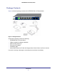
NETGEAR GS110T Smart Switch Package Contents Figure 1 shows the package contents of the NETGEAR GS110T Smart Switch. Figure 1.
NETGEAR GS110T Smart Switch Introduction 10
Physical Description 2. 2 This chapter describes the NETGEAR GS110T Smart Switch hardware features. Topics include: • GS110T Front-Panel Configuration • LED Designations • Device Hardware Interfaces GS110T Front-Panel Configuration The GS110T has eight 10/100/1000 Mbps autosensing and two 1000 Mbps SFP Gigabit Ethernet switching ports. Each RJ-45 port is capable of sensing the line speed and negotiating the duplex mode with the link partner automatically.
NETGEAR GS110T Smart Switch GS110T Back-Panel Configuration Figure 3 illustrates the GS110T back panel. Power Connector Figure 3. GS110T Back Panel The back panel contains the following: • External 12V/1A power adapter for the GS110T LED Designations Port LEDs Table 1 describes the RJ-45 and SFP port LED designations. There are two LEDs for each RJ-45 port. Each SFP port has its own indication LED. Table 1.
NETGEAR GS110T Smart Switch System LEDs Table 2 describes the system LED designations. Table 2. System LEDs LED Designation Power/Status LED • Solid Green = Power is supplied to the switch and the switch is operating normally. • Solid Yellow = The switch is booting. • Off = Power is disconnected. Device Hardware Interfaces RJ-45 Ports RJ-45 ports are autosensing ports.
NETGEAR GS110T Smart Switch Factory Defaults Button The Smart Switch has a Factory Defaults button on the front panel so that you can remove the current configuration and return the device to its factory settings. When you enable the Factory Defaults button, all settings including the password, VLAN settings, and port configurations are removed. To operate the Factory Defaults button, insert a device such as a paper clip into the opening to press the recessed button for two seconds.
3. Applications 3 Your NETGEAR GS110T Smart Switch is designed to provide flexibility in configuring your network connections. It can be used as a stand-alone device or with 10 Mbps, 100 Mbps, and 1000 Mbps hubs and switches. Desktop Switching The GS110T Smart Switch can be used as a desktop switch to build a small network that enables users to have 1000 Mbps access to a file server. With full-duplex enabled, the switch port connected to the server or PC can provide 2000 Mbps throughput.
NETGEAR GS110T Smart Switch Applications 16
4. Installation 4 This chapter describes the installation procedures for your NETGEAR GS110T Smart Switch.
NETGEAR GS110T Smart Switch Table 3. Site Requirements (continued) Characteristics Requirements Power source Provide a power adapter (included). Power specifications for the switch are shown in Appendix A. Ensure the AC outlet is not controlled by a wall switch, which can accidentally turn off power to the outlet and the switch. Environmental • Temperature - Install the switch in a dry area, with ambient temperature between 0ºC and 50ºC (32ºC and 122ºF).
NETGEAR GS110T Smart Switch Step 3: Checking the Installation Before applying power to the switch, perform the following: • Inspect the equipment thoroughly. • Verify that all cables are installed correctly. • Check cable routing to make sure cables are not damaged or creating a safety hazard. • Ensure all equipment is mounted properly and securely. Step 4: Connecting Devices to the Switch The following procedure describes how to connect PCs to the switch’s RJ-45 ports.
NETGEAR GS110T Smart Switch Step 5: Applying AC Power Before connecting the power cord, select an AC outlet that is not controlled by a wall switch, which can turn off power to the switch. After selecting an appropriate outlet, use the following procedure to apply AC power: 1. Connect the end of the supplied IEC AC power adapter cable to the power receptacle on the back of the switch. 2. Connect the AC power adapter cable into a power source such as a wall socket or power strip.
A. Troubleshooting A This chapter provides information about troubleshooting the NETGEAR Smart Switch. Topics include the following: • Troubleshooting Chart • Additional Troubleshooting Suggestions Troubleshooting Chart The following table lists symptoms, causes, and solutions of possible problems. Table 4. Troubleshooting Chart Symptom Cause Solution Power LED is off. No power is received. Check the power adapter connection, the ON/OFF switch, and the connected device.
NETGEAR GS110T Smart Switch Table 4. Troubleshooting Chart (continued) Symptom Cause Solution A segment or device is One or more devices are not recognized as part of not properly connected, the network. or cabling does not meet Ethernet guidelines. Verify that the cabling is correct. Ensure all connectors are securely positioned in the required ports. Equipment may have been accidentally disconnected. ACT LED is flashing continuously on all connected ports and the network is disabled.
B. Technical Specifications Network Protocol and Standards Compatibility IEEE 802.3i 10BASE-T IEEE 802.3u 100BASE-TX IEEE 802.3ab 1000BASE-T IEEE 802.3x flow control IEEE 802.3z 1000BASE-X Management Windows 2000 + XP, Vista; Microsoft Explorer 6.0 or higher IEEE 802.1Q VLAN IEEE 802.3ad Link Aggregation IEEE 802.1D Spanning Tree Protocol IEEE 802.1w Rapid Spanning Tree Protocol IEEE 802.1s Multiple Spanning Trees Protocol IEEE 802.1X Port Security IEEE 802.
NETGEAR GS110T Smart Switch IP and MAC ACL Green feature (Auto power down and Short cable power saving) DoS protection Interface Eight RJ-45 connectors for 10BASE-T, 100BASE-TX, and 1000BASE-T (Auto Uplink™ on all ports) Two SFP slots for SFP modules LEDs Per RJ-45 port: Speed/Link/Activity Per SFP port: SFP indicator Per device: Power Performance Specifications Forwarding modes: Store-and-forward Bandwidth: 20 Gbps Address database size: 4K media access control (MAC) addresses per system Mean Time Betw
NETGEAR GS110T Smart Switch Electromagnetic Emissions FCC Class B CE Class B: Includes EN55022 (CISPR 22), 55024, and 50082-1 VCCI Class B C-Tick KCC CCC Safety UL/cUL CE (includes EN60950) CB Technical Specifications 25
NETGEAR GS110T Smart Switch Technical Specifications 26
Index Numerics G 8-pin 13 Gigabit Ports 7 A H Applying AC Power 20 Auto Uplink 13 Auto-negotiating 8 Autosensing 8, 13 High-speed Servers 7 I IEEE 802.
NETGEAR GS110T Smart Switch R Rack-mount Kit 9 Reset Button 11 RJ-45 8 RJ-45 Ports 13 Rubber footpads 9, 18 S Site Requirements 17 Smart Switch Resource CD 9 Straight-through 13 System LEDs 13 T technical support 2 Temperature 18 trademarks 2 Traffic Control 7 Troubleshooting Chart 21 U User Intervention 13 User’s Manual 9 UTP 19 V Ventilation 18 VLAN 7 W Web-based Graphical User Interface 7 28