User Manual Gigabit Ethernet Plus Switches Models • GS305EP • GS305EPP • GS308EP • GS308EPP January 2021 202-12193-02 NETGEAR, Inc. 350 E.
Gigabit Ethernet Plus Switches Support and Community Visit netgear.com/support to get your questions answered and access the latest downloads. You can also check out our NETGEAR Community for helpful advice at community.netgear.com. Regulatory and Legal Si ce produit est vendu au Canada, vous pouvez accéder à ce document en français canadien à https://www.netgear.com/support/download/. (If this product is sold in Canada, you can access this document in Canadian French at https://www.netgear.
Contents Chapter 1 Hardware Related documentation.......................................................................7 Switch package contents.....................................................................7 Supported switch models....................................................................7 Model GS305EP, GS305EPP, GS308EP, GS308EPP LEDs...............7 Switch label............................................................................................
Gigabit Ethernet Plus Switches Chapter 4 Use VLANS for Traffic Segmentation VLAN overview....................................................................................33 Activate the Basic Port-Based VLAN mode and assign VLANs.....35 Manage advanced port-based VLANs.............................................36 Activate the Advanced Port-Based VLAN Mode........................36 Create an advanced port-based VLAN.......................................37 Change an advanced port-based VLAN............
Gigabit Ethernet Plus Switches Manage the configuration file...........................................................70 Back up the switch configuration.................................................70 Restore the switch configuration..................................................71 Return the switch to its factory default settings..............................72 Use the RESET button to reset the switch...................................72 Use the device UI to reset the switch.......................
1 Hardware This user manual is for the NETGEAR Gigabit Ethernet Plus Switches. For a list of switch models that are supported by this manual, see Supported switch models on page 7. This chapter covers the following topics: • • • • • • Related documentation Switch package contents Supported switch models Model GS305EP, GS305EPP, GS308EP, GS308EPP LEDs Switch label Safety instructions and warnings Note: This user manual complements the installation guide that came with your switch.
Gigabit Ethernet Plus Switches Related documentation The following related documentation is available at netgear.com/support/download/: • Installation guide • Data sheet Switch package contents The package contains the switch, AC power adapter (power cable localized to the country of sale), and installation guide. Supported switch models The Gigabit Ethernet Plus Switches User Manual describes the switch models listed in the following table. Table 1.
Gigabit Ethernet Plus Switches On models GS308EP and GS308EPP, all ports 1 through 8 are PoE+ ports. Table 2. Model GS305EP, GS305EPP, GS308EP, GS308EPP LEDs on the front panel LED Description Power LED Solid green: The switch is powered on and operating normally. Off: Power is not supplied to the switch. PoE Max LED Off: Sufficient (more than 7W of) PoE power is available. Solid yellow: Less than 7W of PoE power is available.
Gigabit Ethernet Plus Switches 5-Port Gigabit Ethernet Smart Managed Plus Switch with PoE+ 產品名稱: 交換器 Model/型號:GS305EP D38488 RoHS R-R-NGR-20300504 NETGEAR INTERNATIONAL LTD Floor 1, Building 3, University Technology Centre Curraheen Road, Cork, T12EF21, Ireland This device complies with part 15 of the FCC Rules.
Gigabit Ethernet Plus Switches • • Observe and follow service markings: - Do not service any product except as explained in your product documentation. Some devices should never be opened. - If applicable to your product, opening or removing covers that are marked with the triangular symbol with a lightning bolt can expose you to electrical shock. We recommend that only a trained technician services components inside these compartments.
Gigabit Ethernet Plus Switches • Be sure that attached devices are electrically rated to operate with the power available in your location. • Depending on your product, use only a supplied power adapter or approved power cable: If your product uses a power adapter: - If you were not provided with a power adapter, contact your local NETGEAR reseller. - The power adapter must be rated for the product and for the voltage and current marked on the product electrical ratings label.
2 Install and Access the Switch in Your Network This chapter describes how you can install and access the switch in your network.
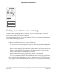
Gigabit Ethernet Plus Switches Set up the switch in your network and power on the switch Figure 1. Example connections To set up the switch in your network and power on the switch: 1. Connect the LAN (UPLINK) port on the switch to a LAN port on a router that is connected to the Internet. On the GS305EP and GS305EPP, use port 5. On the GS308EP and GS308EPP, use port 8. 2. On the switch, connect your PoE devices to the lowest lowest number ports, starting with port 1, and then connect any non-PoE devices.
Gigabit Ethernet Plus Switches Access the switch and discover the IP address of the switch By default, the switch receives an IP address from a DHCP server (or a router that functions as a DHCP server) in your network. For information about setting up a fixed (static) IP address on the switch, see Set up a fixed IP address for the switch on page 15.
Gigabit Ethernet Plus Switches If the NETGEAR Switch Discovery Tool icon is in the Dock of your Mac or on the desktop of your Windows-based computer, click or double-click the icon to open the program. The initial page displays a menu and a button. 8. From the Choose a connection menu, select the network connection that allows the NSDT to access the switch. 9. Click the Start Searching button. The NSDT displays a list of switches that it discovers on the selected network.
Gigabit Ethernet Plus Switches set up a fixed (static) IP address on the switch. This allows you to manage the switch anytime from a mobile device because the switch IP address remains the same. To change the IP address of the switch, you can connect to the switch by one of the following methods: • Through a network connection.
Gigabit Ethernet Plus Switches 6. Enter the fixed (static) IP address that you want to assign to the switch and the associated subnet mask and gateway IP address. You can also either leave the address in the IP Address field as it is (with the IP address that was issued by the DHCP server) or change the last three digits of the IP address to an unused IP address. 7. Write down the complete fixed IP address. You can bookmark it later. 8. Click the APPLY button. Your settings are saved.
Gigabit Ethernet Plus Switches 5. Enter the switch password. The default password is password. The password is case-sensitive. The HOME page displays. The right pane (or, depending on the size of your browser window, the middle pane) shows the IP address that is assigned to the switch. 6. Select IP Address (DHCP On). The button bar in the DHCP section displays green because the DHCP client of the switch is enabled. 7. Click the button in the DHCP section.
Gigabit Ethernet Plus Switches Change the language of the device UI By default, the language of the device UI is set to Auto so that the switch can automatically detect the language. However, you can set the language to a specific one. To change the language of the device UI: 1. Open a web browser from a computer that is connected to the same network as the switch or to the switch directly through an Ethernet cable. 2. Enter the IP address that is assigned to the switch. The login page displays. 3.
Gigabit Ethernet Plus Switches The default password is password. The password is case-sensitive. The HOME page displays. 4. From the menu at the top of the page, select SETTINGS. 5. From the menu on the left, select CHANGE PASSWORD. The CHANGE PASSWORD page displays. 6. In the Current Password field, type the current password for the switch. 7. Type the new password in the New Password field and in the Retype New Password field. 8. Click the APPLY button. Your settings are saved.
3 Optimize the Switch Performance This chapter describes how you can optimize the performance of the switch.
Gigabit Ethernet Plus Switches Set the quality of service mode and port rate limits You can manually set the Quality of Service (QoS) modes to manage traffic: • Port-based QoS mode. Lets you set the priority (low, medium, high, or critical) for individual port numbers and lets you set rate limits for incoming and outgoing traffic for individual ports. If broadcast filtering is enabled, you can also set the storm control rate for incoming traffic for individual ports. • 802.1P/DSCP QoS mode.
Gigabit Ethernet Plus Switches Note: If you set a port rate limit, the actual rate might fluctuate, depending on the type of traffic that the port is processing. To use the Port-based QoS mode and set the priority and rate limits for ports: 1. Open a web browser from a computer that is connected to the same network as the switch, or connected directly to the switch through an Ethernet cable. 2. Enter the IP address that is assigned to the switch. A login window opens. 3.
Gigabit Ethernet Plus Switches The EDIT RATE LIMITS page displays. c. For each port for which you want to set rate limits, select the rate in Kbps or Mbps from the individual In Limits and Out Limits menus for the port. The default selection is No Limit. d. Click the APPLY button. Your settings are saved and the EDIT RATE LIMITS page closes. Use 802.1P/DSCP quality of service In the 802.1P/DSCP QoS mode, the switch uses the 802.
Gigabit Ethernet Plus Switches Note: For information about broadcast filtering, see Manage broadcast filtering and set port storm control rate limits on page 25. 6. To set rate limits, do the following: a. Click the RATE LIMITS tab. If broadcast filtering is disabled, only the RATE LIMITS tab displays. b. Click the purple pencil icon. The EDIT RATE LIMITS page displays. c.
Gigabit Ethernet Plus Switches The Quality of Service (QoS) page displays. 5. If the selection from the QoS Mode menu is not the QoS mode that you want to configure, do the following to change the QoS mode: a. From the QoS Mode menu, select Port-Based or 802.1P/DSCP. A pop-up warning window opens. b. Click the CONTINUE button. The pop-up window closes and the QoS mode is changed. 6. Click the Broadcast Filtering button. When broadcast filtering is enabled, the button bar displays green. 7.
Gigabit Ethernet Plus Switches set the rate limit on a port too low, you might, for example, see degraded video stream quality, sluggish response times during online activity, and other problems. You also can set port rate limits (the same feature) as part of the Quality of Service configuration on the switch (see Set the quality of service mode and port rate limits on page 22). To set rate limits for incoming and outgoing traffic on a port: 1.
Gigabit Ethernet Plus Switches The switch services traffic from ports with a critical priority before traffic from ports with a high, medium, or low priority. Similarly, the switch services traffic from ports with a high priority before traffic from ports with a medium or low priority. If severe network congestion occurs, the switch might drop packets with a low priority.
Gigabit Ethernet Plus Switches You can enable or disable flow control for an individual port. By default, flow control is disabled for all ports. To manage flow control for a port: 1. Open a web browser from a computer that is connected to the same network as the switch, or connected directly to the switch through an Ethernet cable. 2. Enter the IP address that is assigned to the switch. A login window opens. 3. Enter the device management password.
Gigabit Ethernet Plus Switches To change the speed for a port or disable a port: 1. Open a web browser from a computer that is connected to the same network as the switch, or connected directly to the switch through an Ethernet cable. 2. Enter the IP address that is assigned to the switch. A login window opens. 3. Enter the device management password. The password is the one that you specified the first time that you logged in. The user name and password are case-sensitive.
Gigabit Ethernet Plus Switches Your settings are saved. Add or change the name label for a port You can add or change a name label for a port. these name labels. Adding or changing a name label does not change the nature of a port, that is, it is just a label. To add or change a name label for a port: 1. Open a web browser from a computer that is connected to the same network as the switch, or connected directly to the switch through an Ethernet cable. 2.
4 Use VLANS for Traffic Segmentation This chapter describes how you can use VLANs to segment traffic on the switch. The chapter contains the following sections: • • • • • • VLAN overview Activate the Basic Port-Based VLAN mode and assign VLANs Manage advanced port-based VLANs Manage basic 802.1Q VLANs Manage advanced 802.1Q VLANs Deactivate a port-based or 802.
Gigabit Ethernet Plus Switches VLAN overview Virtual LANs (VLANs) are made up of networked devices that are grouped logically into separate networks. You can group ports on a switch to create a virtual network made up of the devices connected to the ports. You can group ports in VLANs using either port-based or 802.1Q criteria: • • Port-based VLANs. Assign ports to virtual networks. Ports with the same VLAN ID are placed in the same VLAN.
Gigabit Ethernet Plus Switches mode can belong to a single VLAN only and does not tag the traffic that it processes. A port that functions in trunk mode automatically belongs to all VLANs on the switch and tags the traffic that it processes. - Advanced 802.1Q VLAN. In an advanced 802.1Q VLAN configuration, VLAN 1 is added to the switch and all ports (1 through 5 for the GS305EP or GS305EPP, and 1 through 8 for the GS308EP or GS308EPP) are untagged members of VLAN 1.
Gigabit Ethernet Plus Switches Table 4. Supported VLAN modes for the GS308EP and GS308EPP (Continued) VLAN Feature Basic Port-Based VLAN Advanced Port-Based VLAN Basic 802.1Q VLAN Advanced 802.1Q VLAN Multiple VLANs on a single port No Yes Yes (trunk port only) Yes Voice VLAN No No No Yes Activate the Basic Port-Based VLAN mode and assign VLANs By default, all types of VLANs are disabled on the switch.
Gigabit Ethernet Plus Switches Your settings are saved and the pop-up window closes. By default, all VLANs are added and each port is a member of VLAN 1. 8. To assign one or more ports to other VLANs, do the following: a. For each port that you want to assign to another VLAN, select a VLAN ID from the VLAN menu for the individual port. Each port can be assigned to a single VLAN only.
Gigabit Ethernet Plus Switches 4. From the menu at the top of the page, select SWITCHING. The QOS page displays. 5. From the menu on the left, select VLAN. The VLAN page displays. 6. In the Advanced Port-Based VLAN section, click the ACTIVATE MODE button. A pop-up window opens, informing you that the current VLAN settings will be lost. 7. Click the CONTINUE button. Your settings are saved and the pop-up window closes. By default, VLAN 1 is added and all ports are members of VLAN 1.
Gigabit Ethernet Plus Switches 6. In the Advanced Port-Based VLAN section, click the ADD VLAN button. 7. Specify the settings for the new VLAN: • VLAN Name. Enter a name from 1 to 14 characters. • VLAN ID. Enter a number from 1 to the total number of ports on the switch. • Ports. Select the ports that you want to include in the VLAN through a combination of the following actions: - Click the icon for an unselected port to add the port to the VLAN.
Gigabit Ethernet Plus Switches The VLAN page displays. 6. In the Advanced Port-Based VLAN section, click the VLAN that you want to change (you can click anywhere in the row for the VLAN) and click the EDIT button. The Advanced Port-Based VLAN pane displays. 7. Change the settings for the VLAN: • VLAN Name. Enter a name from 1 to 14 characters. You cannot change the VLAN ID. If you need to change the VLAN ID, delete the VLAN and create a new VLAN with another VLAN ID. • Ports.
Gigabit Ethernet Plus Switches The password is the one that you specified the first time that you logged in. The password is case-sensitive. The HOME page displays. 4. From the menu at the top of the page, select SWITCHING. The QOS page displays. 5. From the menu on the left, select VLAN. The VLAN page displays. 6. In the Advanced Port-Based VLAN section, click the VLAN that you want to delete (you can click anywhere in the row for the VLAN). 7. Click the DELETE button. Your settings are saved.
Gigabit Ethernet Plus Switches To activate the Basic 802.1Q VLAN mode: 1. Open a web browser from a computer that is connected to the same network as the switch, or connected directly to the switch through an Ethernet cable. 2. Enter the IP address that is assigned to the switch. A login window opens. 3. Enter the device management password. The password is the one that you specified the first time that you logged in. The password is case-sensitive. The HOME page displays. 4.
Gigabit Ethernet Plus Switches To create a basic 802.1Q VLAN and assign ports as members: 1. Open a web browser from a computer that is connected to the same network as the switch, or connected directly to the switch through an Ethernet cable. 2. Enter the IP address that is assigned to the switch. A login window opens. 3. Enter the device management password. The password is the one that you specified the first time that you logged in. The password is case-sensitive. The HOME page displays. 4.
Gigabit Ethernet Plus Switches 7. For a port that functions in access mode, to add a VLAN by using the VLAN menu for the individual port, do the following: a. From the VLAN menu for the individual port, select Add VLAN. The BASIC 802.1Q VLAN pop-up window opens. b. In the VLAN Name field, enter a name from 1 to 14 characters. c. In the VLAN ID field, enter a number from 1 to 4093. d. Click the APPLY button. The pop-up window closes.
Gigabit Ethernet Plus Switches To assign the port mode: 1. Open a web browser from a computer that is connected to the same network as the switch, or connected directly to the switch through an Ethernet cable. 2. Enter the IP address that is assigned to the switch. A login window opens. 3. Enter the device management password. The password is the one that you specified the first time that you logged in. The password is case-sensitive. The HOME page displays. 4.
Gigabit Ethernet Plus Switches The password is the one that you specified the first time that you logged in. The password is case-sensitive. The HOME page displays. 4. From the menu at the top of the page, select SWITCHING. The QOS page displays. 5. From the menu on the left, select VLAN. The VLAN page displays. By default, the Port Configuration tab is selected and the 802.1Q-BASED PORT CONFIGURATION pane displays. 6. To change the name for the VLAN, do the following: a. Click the Edit VLAN button.
Gigabit Ethernet Plus Switches To delete a basic 802.1Q VLAN: 1. Open a web browser from a computer that is connected to the same network as the switch, or connected directly to the switch through an Ethernet cable. 2. Enter the IP address that is assigned to the switch. A login window opens. 3. Enter the device management password. The password is the one that you specified the first time that you logged in. The password is case-sensitive. The HOME page displays. 4.
Gigabit Ethernet Plus Switches • Delete an advanced 802.1Q VLAN Activate the advanced 802.1Q VLAN mode By default, all types of VLANs are disabled on the switch. When you activate the Advanced 802.1Q VLAN mode, VLAN 1 is added to the switch and all ports function as untagged members of VLAN 1. This is the default VLAN in the Advanced 802.1Q VLAN mode. In an advanced 802.1Q VLAN configuration, you can set up VLANs to which you can add tagged or untagged ports.
Gigabit Ethernet Plus Switches 8. To change the port tagging for the default VLAN (VLAN 1), do the following: a. In the table, click 1 or Default (you can click anywhere in the row for VLAN 1). b. Click the EDIT button. c. Select the port tags and whether ports are members of the VLAN through a combination of the following actions: • Click the T button for an individual port to make the port a tagged member of the VLAN.
Gigabit Ethernet Plus Switches 5. From the menu on the left, select VLAN. The VLAN page displays. If you did not yet activate the Advanced 802.1Q VLAN mode, see Activate the advanced 802.1Q VLAN mode on page 47. 6. In the right pane, click the ADD VLAN button. The Advanced 802.1Q VLAN pane displays. 7. Specify the VLAN settings and assign ports as tagged or untagged members: a. In the VLAN Name field, enter a name from 1 to 14 characters. b. In the VLAN ID field, enter a number from 1 to 4094. c.
Gigabit Ethernet Plus Switches 3. Enter the device management password. The password is the one that you specified the first time that you logged in. The password is case-sensitive. The HOME page displays. 4. From the menu at the top of the page, select SWITCHING. The QOS page displays. 5. From the menu on the left, select VLAN. The VLAN page displays. 6. In the table in the right pane, click the VLAN that you want to change (you can click anywhere in the row for the VLAN). 7. Click the EDIT button. 8.
Gigabit Ethernet Plus Switches you connect a computer to port 6 of the switch and you want it to be a part of VLAN 2, add port 6 as a member of VLAN 2 and set the PVID of port 6 to 2. This configuration automatically adds a PVID of 2 to all data that the switch receives from the computer and makes sure that the data from the computer on port 6 can be seen only by other members of VLAN 2. You can assign only one PVID to a port. Note: If you did not yet create an advanced 802.
Gigabit Ethernet Plus Switches The Advanced 802.1Q VLAN pane displays. Set an existing advanced 802.1Q VLAN as the voice VLAN and adjust the CoS value The switch can support a single advanced 802.1Q VLAN as the voice VLAN to facilitate voice over IP (VoIP) traffic. Because a voice VLAN might require a single port to join to multiple VLANs as an untagged member, you can set up a voice VLAN only as an advanced 802.1Q VLAN. For information about creating an advanced 802.1Q VLAN, see Create an advanced 802.
Gigabit Ethernet Plus Switches 8. In the Voice VLAN section, click the button so that the button bar display green. The VLAN is selected to be set as the voice VLAN. 9. From the Class of Service menu, select a CoS value. A value of 0 is the lowest priority and a value of 7 is the highest priority. The default value is 6. For information about viewing and changing the OUI settings, see Change the OUI table for the voice VLAN on page 53. 10. Click the APPLY button. Your settings are saved.
Gigabit Ethernet Plus Switches The VLAN page displays. 6. In the table in the right pane, click Advanced 802.1Q VLAN. 7. Click the EDIT button. 8. In the OUI Table section, click the OUI Settings link. The Voice VLAN pane displays and shows the OUI table. 9. To add a new OUI, do the following: a. Click the ADD OUI button. The OUI Entry page displays. b. Enter the new OUI and description. c. Click the APPLY button. Your settings are saved. 10. To change an existing OUI, do the following: a.
Gigabit Ethernet Plus Switches To delete an advanced 802.1Q VLAN: 1. Open a web browser from a computer that is connected to the same network as the switch, or connected directly to the switch through an Ethernet cable. 2. Enter the IP address that is assigned to the switch. A login window opens. 3. Enter the device management password. The password is the one that you specified the first time that you logged in. The password is case-sensitive. The HOME page displays. 4.
Gigabit Ethernet Plus Switches 4. From the menu at the top of the page, select SWITCHING. The QOS page displays. 5. From the menu on the left, select VLAN. The VLAN page displays. 6. In the NO VLANs section, click the ACTIVATE MODE button. A pop-up window opens, informing you that the current VLAN settings will be lost. 7. Click the CONTINUE button. Your settings are saved, the pop-up window closes, and all VLANs are deleted.
5 Manage the Switch in Your Network This chapter describes how you can manage the switch in your network.
Gigabit Ethernet Plus Switches Manage NETGEAR Switch Discovery Protocol A NETGEAR device or application that supports NETGEAR Switch Discovery Protocol (NSDP) can discover the switch in the network so that you can find the switch IP address and log in to the device UI of the switch. NSDP is enabled by default. You can disable NSDP for security reasons. To manage NSDP: 1.
Gigabit Ethernet Plus Switches Note: The switch does not support Link Aggregation Control Protocol (LACP). You set up static link aggregation on the switch through a LAG in the following order: 1. Set up the LAG on the switch (see Set up a link aggregation group on page 59). 2. Connect the ports that must be members of the LAG on the switch to the ports that must be members of the LAG on another device in your network (see Make a link aggregation connection on page 60). 3.
Gigabit Ethernet Plus Switches A LAG must consist of at least two ports, but can consist of all ports. The number of LAGs that the switch supports depends on the model. 7. Click the APPLY button. Your settings are saved. Make a link aggregation connection Before you make a physical link aggregation connection to another network device (usually a router or another switch) that also supports link aggregation, you must first set up a LAG on the switch (see Set up a link aggregation group on page 59).
Gigabit Ethernet Plus Switches To enable a LAG on the switch: 1. Open a web browser from a computer that is connected to the same network as the switch, or connected directly to the switch through an Ethernet cable. 2. Enter the IP address that is assigned to the switch. A login window opens. 3. Enter the device management password. The password is the one that you specified the first time that you logged in. The password is case-sensitive. The HOME page displays. 4.
Gigabit Ethernet Plus Switches Manage IGMP snooping IGMP snooping is enabled by default. Under some circumstances you might want to temporarily disable IGMP snooping. To manage IGMP snooping: 1. Open a web browser from a computer that is connected to the same network as the switch, or connected directly to the switch through an Ethernet cable. 2. Enter the IP address that is assigned to the switch. A login window opens. 3. Enter the device management password.
Gigabit Ethernet Plus Switches The HOME page displays. 4. From the menu at the top of the page, select SWITCHING > QOS . The Quality of Service (QoS) page displays. 5. From the menu on the left, select MULTICAST. The MULTICAST page displays. 6. In the VLAN ID Enabled for IGMP Snooping section, enter a VLAN ID in the field. If you enabled either a port-based VLAN mode or an 802.1Q VLAN mode, the default VLAN for IGMP snooping is VLAN 1. 7. Click the APPLY button. Your settings are saved.
Gigabit Ethernet Plus Switches 7. Click the APPLY button. Your settings are saved. Manage IGMPv3 IP header validation You can enable IGMPv3 IP header validation so that the switch inspects whether IGMPv3 packets conform to the IGMPv3 standard. By default, IGMPv3 IP header validation is disabled. If IGMPv3 IP header validation is enabled, IGMPv3 messages must include a time-to-live (TTL) value of 1 and a type of service (ToS) byte of 0xC0 (Internetwork Control).
Gigabit Ethernet Plus Switches Set up a static router port for IGMP snooping If your network does not include a device that sends IGMP queries, the switch cannot discover the router port dynamically. (The router port is a port on a device in the network that performs IGMP snooping in the network.) In this situation, select one port on the switch as the dedicated static router port for IGMP snooping, allowing all IGMP Join and Leave messages in the network to be forwarded to this port.
Gigabit Ethernet Plus Switches Change the IP address of the switch By default, the switch receives an IP address from a DHCP server (or a router that functions as a DHCP server) in your network. To disable the DHCP client of the switch and change the IP address of the switch to a fixed IP address: 1. Open a web browser from a computer that is connected to the same network as the switch, or connected directly to the switch through an Ethernet cable. 2. Enter the IP address that is assigned to the switch.
Gigabit Ethernet Plus Switches Reenable the DHCP client of the switch If you disabled the DHCP client of the switch and changed the IP address of the switch to a fixed (static) IP address, you can reverse the situation. To reenable the DHCP client on the switch: 1. Open a web browser from a computer that is connected to the same network as the switch, or connected directly to the switch through an Ethernet cable. 2. Enter the IP address that is assigned to the switch. A login window opens. 3.
6 Maintain and Monitor the Switch This chapter describes how you can maintain and monitor the switch.
Gigabit Ethernet Plus Switches Manually check for new switch firmware and update the switch You can manually check for the latest firmware version, download the firmware, and upload it to the switch. If firmware release notes are available with new firmware, read the release notes to find out if you must reconfigure the switch after updating. To manually check for new switch firmware and update the switch: 1.
Gigabit Ethernet Plus Switches WARNING: Do not interrupt the network connection or power to the switch during the firmware update process. Do not disconnect any Ethernet cables or power off the switch until the firmware update process and switch reboot are complete. Your switch web session is disconnected and you must log back in to the device UI. Manage the configuration file The configuration settings of the switch are stored within the switch in a configuration file.
Gigabit Ethernet Plus Switches Restore the switch configuration If you backed up the configuration file, you can restore the configuration from this file. To restore the configuration settings of the switch: 1. Open a web browser from a computer that is connected to the same network as the switch, or connected directly to the switch through an Ethernet cable. 2. Enter the IP address that is assigned to the switch. A login window opens. 3. Enter the device management password.
Gigabit Ethernet Plus Switches Return the switch to its factory default settings Under some circumstances (for example, if you lost track of the changes that you made to the switch settings or you move the switch to a different network), you might want to erase the configuration and reset the switch to factory default settings. To reset the switch to factory default settings, you can either use the RESET button on the front of the switch or use the reset function in the device UI.
Gigabit Ethernet Plus Switches Use the device UI to reset the switch CAUTION: This process erases all settings that you configured on the switch. To reset the switch to factory default settings using the device UI: 1. Open a web browser from a computer that is connected to the same network as the switch, or connected directly to the switch through an Ethernet cable. 2. Enter the IP address that is assigned to the switch. A login window opens. 3. Enter the device management password.
Gigabit Ethernet Plus Switches 3. Enter the device management password. The password is the one that you specified the first time that you logged in. The password is case-sensitive. The HOME page displays. 4. From the menu at the top of the page, select SETTINGS. 5. From the menu on the left, select ACCESS CONTROL. The ACCESS CONTROL page displays. 6. Click the ADD button. 7. Specify the IP address or IP addresses: • IP Address. Enter a single IP address or a network IP address.
Gigabit Ethernet Plus Switches 4. From the menu at the top of the page, select SETTINGS. 5. From the menu on the left, select ACCESS CONTROL. The ACCESS CONTROL page displays. 6. Click the IP address that you want to remove. The DELETE button displays. 7. Click the DELETE button. The IP address is removed and can no longer access the device UI of the switch. 8. To remove more IP addresses, repeat the previous step.
Gigabit Ethernet Plus Switches Manage the power saving mode The power saving mode enables the IEEE 802.3az Energy Efficient Ethernet (EEE) function, cable length power saving, and link-up and link-down power saving: • IEEE 802.3az. Combines the Energy Efficient Ethernet (EEE) 802.3 MAC sublayer with the 100BASE-TX, 1000BASE-T, and 10GBASE-T physical layers to support operation in Low Power Idle (LPI) mode.
Gigabit Ethernet Plus Switches Control the port LEDs You can turn the port LEDs on the switch on and off by using the device UI. By default, a port LED lights when you connect a powered-on device to the port. When the switch functions with its LEDs off, we refer to it as Stealth Mode. To control the port LEDs through the device UI: 1. Open a web browser from a computer that is connected to the same network as the switch, or connected directly to the switch through an Ethernet cable. 2.
Gigabit Ethernet Plus Switches The password is the one that you specified the first time that you logged in. The password is case-sensitive. The HOME page displays. 4. Select System Info. The System Info fields display. 5. In the Switch Name field, enter a new name for the switch. 6. Click the APPLY button. Your settings are saved. View system information You can view basic information about the switch, such as the firmware version, switch name, MAC address, serial number, and model number.
Gigabit Ethernet Plus Switches A login window opens. 3. Enter the device management password. The password is the one that you specified the first time that you logged in. The user name and password are case-sensitive. The password is case-sensitive. The HOME page displays. The switch connections show in the upper left of the page. View the status of a port You can view the status of and details about a port. To view the status of a port: 1.
Gigabit Ethernet Plus Switches PoE considerations for switches that support PoE A switch that supports Power over Ethernet (PoE) prioritizes the PoE power that it supplies in ascending port order (that is, from the lowest-numbered port to the highest-numbered port), up to its total power budget.
Gigabit Ethernet Plus Switches 3. Enter the device management password. The password is the one that you specified the first time that you logged in. The password is case-sensitive. The HOME page displays. 4. Select POE. The Power over Ethernet (PoE) page displays. 5. To enable or disable the uninterrupted PoE feature, click the Uninterrupted POE button: • Disabled: The button bar displays gray and the button is positioned on the left.
Gigabit Ethernet Plus Switches The port priority determines which ports can still deliver power after the total power delivered by the switch exceeds the total power budget. (In such a situation, the switch might not be able to deliver power to all connected devices.) If the same priority applies to two ports, the lower-numbered port receives higher priority. 10. From the Power Mode menu, select the PoE mode in which the port must function: • 802.3af: The port is powered in and limited to the IEEE 802.
Gigabit Ethernet Plus Switches 12. From the Detection Type menu, select one of the following options: • IEEE 802: The port performs a 4-point resistive detection. This is the default setting. • 4pt 802.3af + Legacy: The port performs a 4-point resistive detection, and if required, continues with legacy detection. • Legacy: The port performs legacy detection. 13. Click the APPLY button. Your settings are saved.
Gigabit Ethernet Plus Switches • Temperature: The temperature in degrees Celcius. • Fault Status: The error description when the PoE port is in a fault state: - No Error: The port is not in any error state and can provide power. - MPS Absent: The port detected the absence of the main power supply, preventing the port from providing power. - Short: The port detected a short circuit condition, preventing the port from providing power.
Gigabit Ethernet Plus Switches The Power over Ethernet (PoE) page displays. 5. Forcibly reset a PoE port by clicking the port number. When the port is selected, the port button displays solid purple. 6. Click the APPLY button. The PoE on the port is forcibly reset.
7 Diagnostics and Troubleshooting This chapter covers the following topics: • • • Test cable connections Resolve a subnet conflict to access the switch PoE troubleshooting suggestions 86
Gigabit Ethernet Plus Switches Test cable connections You can use the cable diagnostic feature to easily find out the health status of network cables. If any problems exist, this feature helps quickly locate the point where the cabling fails, allowing connectivity issues to be fixed much faster, potentially saving technicians hours of troubleshooting. If an error is detected, the distance at which the fault is detected is stated in meters. (This is the distance from the port.) To test cable connections: 1.
Gigabit Ethernet Plus Switches be different from the subnet used in your network. You might see the following message if you try to access the switch: The switch and manager IP address are not in the same subnet. To resolve this subnet conflict: 1. Disconnect the Ethernet cable between the switch and your network. 2. Shut down power to the switch. 3. Reconnect the Ethernet cable between the switch and your network. 4. Reapply power to the switch. The switch powers on.
A Factory Default Settings and Technical Specifications This appendix contains the following sections: • • Factory default settings Technical specifications 89
Gigabit Ethernet Plus Switches Factory default settings You can return the switch to its factory settings. Use the end of a paper clip or some other similar object to press and hold the Reset button on the front panel of the switch for at least ten seconds. The switch resets and returns to the factory settings that are shown in the following table. Table 7. Factory default settings Feature Setting Switch password password IP address 192.168.0.
Gigabit Ethernet Plus Switches Technical specifications This section describes the technical specifications for each switch model. Model GS305EP and GS308EP technical specifications The following table shows the technical specifications for models GS305EP and GS308EP. Table 8.
Gigabit Ethernet Plus Switches Table 9. Models GS305EPP and GS308EPP technical specifications Feature Description Network interface RJ-45 connector for 10BASE-T, 100BASE-TX, or 1000BASE-T Network cable Category 5e (Cat 5e) or higher-rated Ethernet cable Ethernet ports 5 for GS305EPP and 8 for GS308EPP Power input 54V, 2.4A DC input Power consumption GS305EPP: 4.5W (no PoE), 137.8W (with PoE max) GS308EPP: 5.9W (no PoE), 141.4W (with PoE max) Dimensions (W x D x H) 6.2 x 4.0 x 1.
B Additional Switch Discovery and Access Information This appendix provides additional information about how you can discover and access the switch in your network.
Gigabit Ethernet Plus Switches Access the switch from any computer This procedure requires you to use an IP scanner application. Such applications are available on the Internet, and some of them are free of charge. To discover the switch IP address and access the switch from a computer: 1. From a computer that is connected to your network, run the IP scanner application in your network. The IP address that is assigned to the switch displays in the IP scanner application.