R 8 PORT 10/100/1000 Mbps Copper Gigabit Switch Installation Guide MODEL GS 508T
© 2001 by NETGEAR, Inc. All rights reserved. Trademarks NETGEAR is a trademark of NETGEAR, Inc. All other trademarks and registered trademarks are the property of their respective owners. Statement of Conditions In the interest of improving internal design, operational function, and/or reliability, NETGEAR reserves the right to make changes to the products described in this document without notice.
Federal Communications Commission (FCC) Compliance Notice: Radio Frequency Notice This device complies with part 15 of the FCC Rules. Operation is subject to the following two conditions: • This device may not cause harmful interference. • This device must accept any interference received, including interference that may cause undesired operation. Note: This equipment has been tested and found to comply with the limits for a Class A digital device, pursuant to part 15 of the FCC Rules.
Customer Support For assistance with installing and configuring your NETGEAR system or with questions or problems following installation: • Check the NETGEAR Web page at http://www.NETGEAR.com. • Call Technical Support at the phone number listed on the Support Information Card that shipped with your switch. • Email Technical Support at support@NETGEAR.com. Defective or damaged merchandise can be returned to your point-of-purchase representative.
CONTENTS CHAPTER 1 Introduction Features Package Contents 1-1 1-2 CHAPTER 2 Physical Description Front Panel LEDs Rear Panel 2-1 2-2 2-2 CHAPTER 3 Applications Desktop Switching Segment Switching and Bridging from 100 Mbps to 1000 Mbps 3-1 3-2 CHAPTER 4 Installation Preparing the Site Installing the Switch on a Flat Surface Installing the Switch in a Rack Connecting Devices to the Switch Verifying Installation 4-1 4-1 4-2 4-2 4-3 CHAPTER 5 Troubleshooting APPENDIX A Technical Specifications content
APPENDIX B Connector Pin Assignments RJ-45 Plug and RJ-45 Connector B-1 APPENDIX C Cabling Guidelines Using 1000BASE-T Gigabit Ethernet over Category 5 Cable Overview Cabling Length Return Loss Near End Cross Talk (NEXT) Patch Cables Conclusions Fast Ethernet Cable guidelines Category 5 Cable Category 5 Cable Specifications Twisted Pair Cables for 1000BASE-TX Patch Panel and cables C-1 C-1 C-1 C-1 C-2 C-2 C-3 C-3 C-3 C-4 C-4 C-5 C-6 contents vi
FIGURES Figure 1-1. Model GS508T Switch Package Contents 1-2 Figure 2-1. Front Panel of the Model GS508T Switch 2-1 Figure 2-2. Rear Panel of the Model GS508T Switch 2-2 Figure 3-1. Model GS508T Switch Used as a Desktop Switch 3-1 Figure 3-2. Model GS508T Switch Used as a Segment Switch 3-2 Figure 4-1. Attaching Mounting Brackets 4-2 Figure 4-2. Connecting to the Model GS508T Switch 4-3 Figure B-1. RJ-45 Plug and RJ-45 Connector with Built-in LEDs B-1 Figure C-1.
TABLES Table 2-1. LED Descriptions 2-2 Table 4-1. Operating Environment Requirements 4-1 Table 5-1. Troubleshooting Information 5-1 Table B-1. 10/100/1000 Mbps RJ-45 Plug and RJ-45 Connector Pin Assignments B-2 Electrical Requirements of Category 5 Cable C-4 Table C-1.
CHAPTER 1: INTRODUCTION R The NETGEAR Model GS508T 8-Port Copper Gigabit Switch provides you with a low-cost, high-performance network solution and is designed to anchor and interconnect 10/100/1000 megabits per second (Mbps) workgroups using copper Gigabit links.
Package Contents Figure 1-1 illustrates the Model GS508T switch package contents. Figure 1-1.
CHAPTER 2: PHYSICAL DESCRIPTION This chapter describes the hardware features of the NETGEAR Model GS508T Copper Gigabit Switch. Front Panel The front panel of the Model GS508T switch contains the following LEDs that correspond to each network port: Activity (Rx/Tx), FDX/COL (full-duplex/collision), and 10Mbps speed. Each network port has its own link LED (located above each 100/1000 Mbps port). Figure 2-1.
LEDs Table 2-1 describes the activity of the LEDs. Table 2-1. LED Descriptions Label Color Activity Description Power Green On Power is supplied to the switch. Off Power is disconnected. On The port is operating in full-duplex mode. Off The port is operating in half-duplex mode. Yellow Blinking Data collisions are occurring on the port. In a full-duplex environment, there is no collision. In a half-duplex environment, some collisions are normal.
CHAPTER 3: APPLICATIONS This chapter presents an overview of the levels of service provided by incorporating the technology of the NETGEAR Model GS508T Copper Gigabit Switch into your network. Desktop Switching Figure 3-1 illustrates the Model GS508T switch, used as a desktop switch to build a powerful network that enables users to have 1000 Mbps access to a file server. If a full-duplex adapter card is installed in the server or PC, a 2000 Mbps connection will be provided to each server and PC.
Segment Switching and Bridging from 100 Mbps to 1000 Mbps The Model GS508T switch, as illustrated in Figure 3-2, connects multiple power workgroups and servers using high-speed gigabit links. Each power workgroup is anchored by a NETGEAR Model FS510T switch. Because each copper link can be up to 100 m long, these workgroups can be located on separate floors or in different buildings. Figure 3-2.
CHAPTER 4: INSTALLATION This chapter describes the installation procedures for the NETGEAR Model GS508T Copper Gigabit Switch. Preparing the Site Before you begin installing your switch, prepare the installation site. Make sure your operating environment meets the operating environment requirements of the equipment listed in Table 4-1. Table 4-1. Operating Environment Requirements Characteristic Requirements Temperature Ambient temperature between 0 and 40ºC (32 and 104ºF).
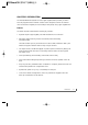
Installing the Switch in a Rack Refer to Figure 4-1 when installing the switch in a rack. 100/1000 Mbps Copper Gigabit Switch Power Ethern et MODEL GS50 4T 9378FB Figure 4-1. Attaching Mounting Brackets Connecting Devices to the Switch To connect the switch: 1. Connect the devices to the network ports on the switch, using Category 5 (Cat5) or Category 5e (Cat5e) UTP cable. Note: Ethernet specifications limit the cable length between your PC or server and the switch to 100 m. 2.
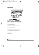
Key 1000 Mbps 100 Mbps 4POR T 10/10 0Mbp sGiga bit Fibe r Swit ch Eth erne t MODEL GS 508 T 9330FB Figure 4-2. Connecting to the Model GS508T Switch Verifying Installation When power has been applied to the switch, verify that: • The green power LED on the front panel is on. • The green link LED on each connected port is on. When the switch is connected and operating, refer to Table 2-1 “LED Descriptions” for information about the LEDs and their activity.
CHAPTER 5: TROUBLESHOOTING This chapter provides information about troubleshooting the NETGEAR Model GS508T Copper Gigabit Switch. Table 5-1 lists symptoms, causes, and solutions of possible problems. Table 5-1. Troubleshooting Information Symptom Cause Solution Power LED is off. No power is received at the switch. Check the power cord connections for the switch and the connected device. Make sure all cables used are correct and comply with Ethernet specifications.
APPENDIX A: TECHNICAL SPECIFICATIONS This appendix provides technical specifications for the NETGEAR Model GS508T Copper Gigabit Switch. Network Protocol and Standards Compatibility IEEE 802.3ab 1000BASE-T IEEE 802.3u 100BASE-TX IEEE 802.3i 10BASE-T IEEE 802.
Power Consumption 60 W Input Voltage (Power Adapter) 100–240 V AC Physical Specifications Dimensions: 13.0 x 1.7 x 8.0 in.; 33.0 x 4.3 x 20.7 cm Weight: 5.3 lb; 2.
APPENDIX B: CONNECTOR PIN ASSIGNMENTS This appendix provides information about the RJ-45 plug and the RJ-45 connector used for the NETGEAR Model GS508T Copper Gigabit Switch. RJ-45 Plug and RJ-45 Connector It is important that all 1000 BASE-T certified Category 5 or Category 5e cabling use RJ-45 plugs.The RJ-45 plug accepts 4-pair UTP or shielded twisted pair (STP) 100 ohm cable and connects into the RJ-45 connector.
Table B-1 lists the pin assignments for the 10/100/1000Mbps RJ-45 plug and the RJ-45 connector. Table B-1.
APPENDIX C: CABLING GUIDELINES This appendix provides specifications for cables used with the NETGEAR Model GS508T Copper Gigabit Switch. Using 1000BASE-T Gigabit Ethernet over Category 5 Cable Overview When using the new 1000BASE-T standard, the limitations of cable installations and the steps necessary to ensure optimum performance must be considered.
Return Loss Return loss measures the amount of reflected signal energy resulting from impedance changes in the cabling link.The nature of 1000BASE-T renders this measurement very important; if too much energy is reflected back on to the receiver, the device will not perform optimally. All four pairs of the twisted pair are used by 1000BASE-T, unlike 10BASE-T and 100BASE-TX, which use only two of the four pairs of wires within the Category 5. It is important to ensure that all wires are tested.
Patch Cables When installing your equipment, replace old patch panel cables that do not meet Category 5e specifications. As pointed out in the NEXT section, this near end piece of cable is critical for successful operation. Conclusions For optimum performance of your 1000BASE-T product, it is important to fully qualify your cable installation and ensure it meets or exceeds ANSI/EIA/TIA568-A:1995 or ISO/IEC 11801:1995 Category 5 specifications.
Category 5 Cable Category 5 distributed cable that meets ANSI/EIA/TIA-568-A building wiring standards can be a maximum of 328 feet (ft) or 100 meters (m) in length, divided as follows: • 20 ft (6 m) between the hub or switch and the patch panel (if used) • 295 ft (90 m) from the wiring closet to the wall outlet • 10 ft (3 m) from the wall outlet to the desktop device The patch panel and other connecting hardware must meet the requirements for 100 Mbps operation (Category 5). Only 0.5 inch (1.
Twisted Pair Cables for 100 BASE-TX For two devices to communicate, the transmitter of each device must be connected to the receiver of the other device.The crossover function is usually implemented internally as part of the circuitry in the device. Computers and workstation adapter cards are usually media-dependent interface ports, called MDI or uplink ports. Most repeaters and switch ports are configured as media-dependent interfaces with built-in crossover ports, called MDI-X or normal ports.
Patch Panels and Cables If you are using patch panels, make sure that they meet the 100BASE-TX requirements. NETGEAR recommends Category 5e UTP cable for all patch cables and work area cables to ensure that your UTP patch cable rating meets or exceeds the distribution cable rating. To wire patch panels, you need two Category 5e UTP cables with an RJ-45 plug at each end, as shown in Figure C-3. 1 2 1 87654321 87654321 Key: 1 = RJ-45 plug 2 = Category 5e UTP patch cable 5525.1 Figure C-3.
cabling guidelines C-7
R NETGEAR, Inc. 4500 Great America Parkway Santa Clara, CA 95054 USA Phone: 1-888-NETGEAR www.NETGEAR.