GS700AT Series Hardware Installation Guide NETGEAR, Inc.
© 2008 by NETGEAR, Inc. All rights reserved. FullManual. Technical Support Please refer to the support information card that shipped with your product. By registering your product at http://www.netgear.com/register, we can provide you with faster expert technical support and timely notices of product and software upgrades. NETGEAR, INC. Support Information Phone: 1-888-NETGEAR, for US & Canada only. For other countries, see your Support information card. E-mail: support@netgear.
Voluntary Control Council for Interference (VCCI) Statement This equipment is in the Class B category (information equipment to be used in a residential area or an adjacent area thereto) and conforms to the standards set by the Voluntary Control Council for Interference by Data Processing Equipment and Electronic Office Machines aimed at preventing radio interference in such residential areas. When used near a radio or TV receiver, it may become the cause of radio interference.
with the instructions, may cause harmful interference to radio communications. However, there is no guarantee that interference will not occur in a particular installation.
Contents About This Guide Conventions, Formats and Scope ....................................................................................vii How to Use This Manual .................................................................................................viii How to Print this Manual ..................................................................................................viii Revision History ................................................................................................
GS700AT Hardware Installation Guide Port LEDs .................................................................................................................3-3 System LEDS ...........................................................................................................3-3 Device Hardware Interfaces ...........................................................................................3-4 RJ-45 Ports ............................................................................................
About This Guide Congratulations on the purchase of the NETGEAR Smart Switch. The NETGEAR® GS700AT Installation Manual describes how to install, configure and troubleshoot the smart switch. The information in this manual is intended for readers with intermediate computer and Internet skills. Conventions, Formats and Scope The conventions, formats, and scope of this manual are described in the following paragraphs: • • Typographical Conventions.
GS700AT Hardware Installation Guide Danger: This is a safety warning. Failure to take heed of this notice may result in personal injury or death. • Scope. This manual is written for the GS700AT according to these specifications: Product Version GS700AT Smart Switch Manual Publication Date October 2008 Note: Product updates are available on the NETGEAR, Inc. web site at http://kbserver.netgear.com How to Use This Manual The HTML version of this manual includes the following: • Buttons, at a time.
GS700AT Hardware Installation Guide – – – Click the PDF of This Chapter link at the top right of any page in the chapter you want to print. The PDF version of the chapter you were viewing opens in a browser window. Your computer must have the free Adobe Acrobat reader installed in order to view and print PDF files. The Acrobat reader is available on the Adobe Web site at http://www.adobe.com. Click the print icon in the upper left of the window.
GS700AT Hardware Installation Guide x About This Guide v1.
Chapter 1 Introduction The NETGEAR Smart Switch is a state-of-the-art, high-performance, IEEE-compliant network solution designed for users who require a large number of ports and want the power of Gigabit connectivity to eliminate bottlenecks, boost performance, and increase productivity. To simplify installation, the switch is shipped ready for use out of the box.
GS700AT Hardware Installation Guide and Class of Service (CoS) for traffic prioritization. These features provide better understanding and control of the network. Initial discovery of the switch on the network requires the Smart Wizard Discovery program, a utility that runs on a PC. The GS700AT Smart Switch can be free-standing, or rack mounted in a wiring closet or equipment room. It is IEEE-compliant and offers low latency for high-speed networking.
GS700AT Hardware Installation Guide Switch Features The following list identifies the key features of the NETGEAR Smart Switch. • On the GS724AT device there are 24 RJ-45 ports10/100/1000M auto sensing Gigabit Ethernet switching ports, four of which are Combo ports. • On the GS748AT device there are 48 RJ-45 ports 10/100/1000M auto sensing Gigabit Ethernet switching ports, four of which are Combo ports. • Four Small Form-factor Pluggable (SFP) GBIC slots, which function as combo ports.
GS700AT Hardware Installation Guide • Active flow control to minimize packet loss/frame drops. • Half-duplex back-pressure control. • Per port LEDs, System LEDs. • Internal power supply. • Standard 1U high, rack mountable 19”chassis. • Fan speed control supported (optional). Package Contents Figure 1-2 shows the NETGEAR Smart Switch package contents.
GS700AT Hardware Installation Guide • Smart Switch Resource CD with Smart Wizard Discovery and User’s manual • Warranty/Support Information Card If any item is missing or damaged, contact the place of purchase immediately. Introduction 1-5 v1.
GS700AT Hardware Installation Guide 1-6 Introduction v1.
Chapter 2 Installation This chapter describes the installation procedures for your NETGEAR Smart Switch.
GS700AT Hardware Installation Guide Table 2-1. Site Requirements (continued) Characteristics Requirements Power source Provide a power source within 6 feet (1.8 meters) of the installation location. Power specifications for the switch are shown in Appendix A, “Troubleshooting”. Ensure the AC outlet is not controlled by a wall switch, which can accidentally turn off power to the outlet and the switch.
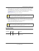
GS700AT Hardware Installation Guide 5. Tighten the screws with a #2 Phillips screwdriver to secure the switch in the rack. Figure 2-1 Note: Always install devices from the bottom of the to the top. This will prevent the rack from over balancing and toppling over. Step 3: Checking the Installation Before applying power perform the following: • Inspect the equipment thoroughly. • Verify that all cables are installed correctly.
GS700AT Hardware Installation Guide Step 4: Connecting Devices to the Switch The following procedure describes how to connect PCs to the switch’s RJ-45 ports. The NETGEAR Smart Switch contains Auto Uplink™ technology, which allows you to attach devices using either straight-through or crossover cables. Figure 2-2 Connect each PC to an RJ-45 network port on the Switch front panel (Figure 2-2).
GS700AT Hardware Installation Guide To install an SFP GBIC module: 1. Insert the SFP module into the SFP module bay. 2. Press firmly to ensure the module seats into the connector. Figure 2-3 Step 6: Applying AC Power NETGEAR Smart Switch does not have an ON/OFF switch. The method of applying or removing AC power is by connecting or disconnecting the power cord.
GS700AT Hardware Installation Guide Step 7: Managing the Switch through a Web Browser or the PC Utility for Initial Configuration The NETGEAR Smart Switch contains software for viewing, changing, and monitoring the way it works. This management software is not required for the switch to work. You can use the ports without using the management software.
Chapter 3 Physical Description This chapter describes the NETGEAR Smart Switch hardware features. The topics include: • “Front and Back Panel Configuration” • “LED Designations” • “Device Hardware Interfaces” Front and Back Panel Configuration GS724AT Front Panel The GS724AT is a 24-Ports 10/100/1000M + 4 SFP Combo ports Smart switch. Every RJ45 port is capable of sensing the line speed and negotiating the operation duplex mode with the link partner automatically.
GS700AT Hardware Installation Guide GS748AT Front Panel The GS748AT is a 48-Ports 10/100/1000M + 4 SFP Combo ports Smart switch. Every RJ45 port is capable of sensing the line speed and negotiating the operation duplex mode with the link partner automatically. Figure 3-2 illustrates the NETGEAR GS748AT Smart Switch front panel. Figure 3-2 The front panel contains the following: • 48 RJ-45 connectors for 10/100/1000Mbps auto sensing Gigabit Ethernet switching ports.
GS700AT Hardware Installation Guide LED Designations This section provides an explanation for the following LED types: • “Port LEDs” • “System LEDS” Port LEDs The following table describes the port LED designations. Table 3-1. Port LEDs Port LED Designation 24/48-10/100/1000 Ports - One LED/Port Link/ACT LED • Off - No 10/100/1000Mbps link is established on the port. • Solid Green - A valid 1000Mbps link is established on the port.
GS700AT Hardware Installation Guide Table 3-2. System LEDs LED Designation Power LED • Off - Power is disconnected. • Solid Green - Power is supplied to the switch and is operating normally. FAN LED • Off - FAN is operating normally. • Solid Yellow - FAN has failed. Device Hardware Interfaces This section provides information for the following hardware interfaces: • “RJ-45 Ports” • “SFP GBIC Module” • “Factory Defaults Button” RJ-45 Ports RJ-45 ports are auto-sensing ports.
GS700AT Hardware Installation Guide SFP GBIC Module The GBIC module bays accommodate standard SFP GBIC modules, such as the AGM731F, AGM732F, or AGM733 from NETGEAR, allowing fiber connections on the network. The module bay is a combo port, sharing a connection with an RJ-45 port. Being a combo port, only one type of connection can be active at any given time. For example, both copper and fiber port cannot be used at the same time.
GS700AT Hardware Installation Guide 3-6 Physical Description v1.
Appendix A Troubleshooting This chapter provides information about troubleshooting the NETGEAR Smart Switch. The topics include the following: • “Troubleshooting Chart” • “Additional Troubleshooting Suggestions” Troubleshooting Chart The following table lists symptoms, causes, and solutions of possible problems. Table A-1. Troubleshooting Chart Symptom Cause Solution Power LED is off. No power is received. Check the power cord connections for the switch at the switch and the connected device.
GS700AT Hardware Installation Guide Table A-1. Troubleshooting Chart (continued) Symptom Cause Solution A segment or device is not recognized as part of the network. One or more devices are not properly connected, or cabling does not meet Ethernet guidelines. Verify that the cabling is correct. Ensure all connectors are securely positioned in the required ports. Equipment may have been accidentally disconnected. ACT LED is flashing continuously on all connected ports and the network is disabled.
GS700AT Hardware Installation Guide Auto-negotiation The RJ-45 ports negotiate the correct duplex mode and speed if the device at the other end of the link supports auto-negotiation. If the device does not support auto negotiation, the switch only determines the speed correctly and the duplex mode defaults to half-duplex. The gigabit port on the Gigabit module negotiates speed, duplex mode, and flow control, provided that the attached device supports auto-negotiation. Troubleshooting A-3 v1.
GS700AT Hardware Installation Guide A-4 Troubleshooting v1.
Appendix B Technical Specifications Network Protocol and Standards Compatibility IEEE 802.3i 10Base-T IEEE 802.3u 100Base-TX,FX IEEE 802.3ab 1000Base-T IEEE 802.3z 1000Base-X IEEE 802.3x flow control Management IEEE 802.1Q Static VLAN (Up to 128 ranging from 2 to 4K) Windows 2000 + XP; Microsoft Explorer 6.0 IEEE 802.1p Class of Service (CoS) Interface 24/48-RJ-45 connectors for 10Base-T,100Base-TX and 1000Base-(Auto Uplink™ on all ports).
GS700AT Hardware Installation Guide Power Consumption: 68W for GS748AT 100-240VAC/50-60 Hz universal input Physical Specifications Dimensions (H x W x D): GS724AT: 1.7 x 17.3 x 8.1 / 43 x 440 x 205 (in/mm) Dimensions (H x W x D): GS748AT: 1.7 x 17.3 x 10.1 / 43 x 440 x 257 (in/mm) Weight: GS724AT: 6.835 / 3.1 (lbs/kg) Weight: GS748AT: 11.0 / 5.
GS700AT Hardware Installation Guide Safety CE mark, commercial UL/cUL listed (UL 1950) / CUL IEC950 / EN60950 Modules AGM731F 1000Base-SX SFP GBIC for multimode fiber AGM732F 1000Base-LX SFP GBIC for single mode fiber AGM733 1000Base-LZ GBIC for long haul single mode fiber Technical Specifications B-3 v1.
GS700AT Hardware Installation Guide B-4 Technical Specifications v1.
Index Numerics Class of Service 1-2 1000Base-LX 1-2 Combo Port 2-10 1000Base-SX 1-2 Combo Ports 1-2 1000Base-T 1-2 Connecting Devices to the Switch 4-16 1000Base-X 1-2 Copper 1-1 100-240VAC/50-60 2-6 Crossover 2-9 100Base-TX 1-2 10Base-T 1-2 D 1U 1-3 Default IP Address 4-18 8-pin 2-9 Default Reset Button 2-5, 2-7 Device Hardware Interfaces 2-9 A AC Power 2-6, 2-7 Duplex Mode 2-9 AGM731F 2-10 E AGM732F 2-10 Example of Desktop Switching 3-12 AGM733 2-10 Applying AC Power 4-17 F Atta
GS700TP Hardware Installation Guide Hz 2-6, 2-7 I P Package Contents 1-4 Pause Frame Flow Control 1-3 IEEE 802.3ab 1-2 Phillips Screwdriver 4-14 IEEE 802.3i 1-2 Port LEDs 2-8 IEEE 802.3u 1-2 Power cord 1-4 IEEE 802.3x 1-2, 1-3 Preparing the Site 4-13 IEEE 802.
GS700TP Hardware Installation Guide User’s Manual 1-4 UTP 4-16 V Ventilation 4-14 VLAN 1-1 W Warranty 1-4 Web-based Graphical User Interface 1-1 Index-3 v1.
Index-4 v1.