
User Manual

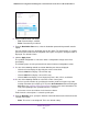


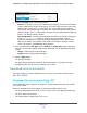
Table Of Contents
- 24-Port Gigabit Smart Managed Pro Switch with PoE+ and 2 SFP Ports Model GS724TPv2
- Contents
- 1. Get Started
- Switch Management Interface Overview
- Change the Default IP Address of the Switch
- Discover a Switch in a Network With a DHCP Server
- Discover a Switch in a Network Without a DHCP Server
- Configure the Network Settings on Your Computer
- Access the Web Browser–Based Management Interface
- About the User Interfaces
- Use a Web Browser to Access the Switch and Log In
- Web Browser–Based Management Interface Device View
- Interface Naming Conventions
- Configure Interface Settings
- Context-Sensitive Help and Access to the Support WebSite
- Register Your Product
- 2. Configure System Information
- 3. Configure Switching
- Configure Port Settings
- Configure Link Aggregation Groups
- Configure VLANs
- Configure a Voice VLAN
- Configure Auto-VoIP
- Configure Spanning Tree Protocol
- Configure Multicast
- View the MFDB Table
- View the MFDB Statistics
- IGMP Snooping Overview
- Configure IGMP Snooping
- Configure IGMP Snooping for Interfaces
- View the IGMP Snooping Table
- Configure IGMP Snooping for VLANs
- Modify IGMP Snooping Settings for a VLAN
- IGMP Snooping Querier Overview
- Configure IGMP Snooping Querier
- Configure IGMP Snooping Querier for VLANs
- Display IGMP Snooping Querier for VLAN Status
- Configure a Static Multicast Group
- Remove a Static Multicast Group
- Configure Multicast Group Membership
- Configure the Multicast Forward All Option
- View and Configure the MAC Address Table
- 4. Configure Quality of Service
- 5. Manage Device Security
- Configure the Management Security Settings
- Configure Management Access
- Configure Port Authentication
- Configure Traffic Control
- Configure Access Control Lists
- Use the ACL Wizard to Create a Simple ACL
- Configure a MAC ACL
- Configure MAC ACL Rules
- Configure MAC Bindings
- View or Delete MAC ACL Bindings in the MAC Binding Table
- Configure an IP ACL
- Configure Rules for a Basic IP ACL
- Configure Rules for an Extended IP ACL
- Configure IP ACL Interface Bindings
- View or Delete IP ACL Bindings in the IP ACL Binding Table
- 6. Monitor the System
- 7. Maintenance
- A. Configuration Examples
- B. Specifications and Default Settings
Monitor the System
273
NETGEAR 24-Port Gigabit Smart Managed Pro Switch with PoE+ and 2 SFP Ports Model GS724TPv2
6. Select an Admin Mode radio button:
• True. Port mirroring is enabled.
• False. Port mirroring is enabled.
7. From the Destination Port menu, select the destination port to which port traffic must be
copied.
You can configure only one destination port on the switch. The port functions as a probe
port and receives traffic from all configured source ports. If no port is configured, None is
displayed. The default is None.
8. Click the Apply button.
The updated configuration is sent to the switch. Configuration changes take effect
immediately.
The following steps must be performed in the Source Interface Configuration section.
9. Use one of the following methods to narrow down the ports that are displayed:
• Click the 1 link to display the physical ports of the selected unit.
• Click the LAG link to display a list of LAGs only.
• Click the CPU link to display a list of CPUs only.
• Click the All link to display a list of all physical ports, LAGs, CPUs, and VLANs.
10. Use one of the following methods to select one or more source ports:
• Select a specific interface by specifying the interface number using the respective
naming convention (for example, g1 or l1) in the Go To Interface field and clicking the
Go button. See Interface Naming Conventions on page 21 for more information. The
entry corresponding to the specified interface is selected.
• Select one or more check boxes in the Interface column.
Traffic from the selected ports is sent to the probe port.
11. From the Direction menu, specify the direction of the traffic that must be mirrored from the
selected source ports:
• None. The value is not configured. This is the default setting.