
User Manual
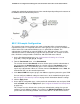
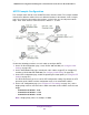
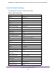
Table Of Contents
- 24-Port Gigabit Smart Managed Pro Switch with PoE+ and 2 SFP Ports Model GS724TPv2
- Contents
- 1. Get Started
- Switch Management Interface Overview
- Change the Default IP Address of the Switch
- Discover a Switch in a Network With a DHCP Server
- Discover a Switch in a Network Without a DHCP Server
- Configure the Network Settings on Your Computer
- Access the Web Browser–Based Management Interface
- About the User Interfaces
- Use a Web Browser to Access the Switch and Log In
- Web Browser–Based Management Interface Device View
- Interface Naming Conventions
- Configure Interface Settings
- Context-Sensitive Help and Access to the Support WebSite
- Register Your Product
- 2. Configure System Information
- 3. Configure Switching
- Configure Port Settings
- Configure Link Aggregation Groups
- Configure VLANs
- Configure a Voice VLAN
- Configure Auto-VoIP
- Configure Spanning Tree Protocol
- Configure Multicast
- View the MFDB Table
- View the MFDB Statistics
- IGMP Snooping Overview
- Configure IGMP Snooping
- Configure IGMP Snooping for Interfaces
- View the IGMP Snooping Table
- Configure IGMP Snooping for VLANs
- Modify IGMP Snooping Settings for a VLAN
- IGMP Snooping Querier Overview
- Configure IGMP Snooping Querier
- Configure IGMP Snooping Querier for VLANs
- Display IGMP Snooping Querier for VLAN Status
- Configure a Static Multicast Group
- Remove a Static Multicast Group
- Configure Multicast Group Membership
- Configure the Multicast Forward All Option
- View and Configure the MAC Address Table
- 4. Configure Quality of Service
- 5. Manage Device Security
- Configure the Management Security Settings
- Configure Management Access
- Configure Port Authentication
- Configure Traffic Control
- Configure Access Control Lists
- Use the ACL Wizard to Create a Simple ACL
- Configure a MAC ACL
- Configure MAC ACL Rules
- Configure MAC Bindings
- View or Delete MAC ACL Bindings in the MAC Binding Table
- Configure an IP ACL
- Configure Rules for a Basic IP ACL
- Configure Rules for an Extended IP ACL
- Configure IP ACL Interface Bindings
- View or Delete IP ACL Bindings in the IP ACL Binding Table
- 6. Monitor the System
- 7. Maintenance
- A. Configuration Examples
- B. Specifications and Default Settings
Configuration Examples
305
NETGEAR 24-Port Gigabit Smart Managed Pro Switch with PoE+ and 2 SFP Ports Model GS724TPv2
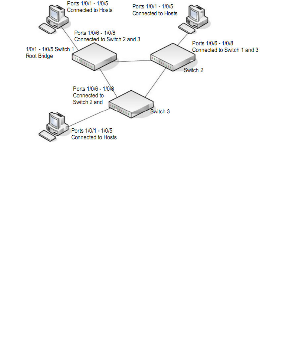
MSTP Example Configuration
This example shows how to create an MSTP instance from the switch. The example network
includes three different switches that serve different locations in the network. In this example,
ports 1/0/1–1/0/5 are connected to host stations, so those links are not subject to network
loops. Ports 1/0/6–1/0/8 are connected across switches 1, 2, and 3.
Figure 2. MSTP sample configuration
Perform the following procedures on each switch to configure MSTP:
1. On the VLAN Configuration page, create VLANs 300 and 500 (see Configure VLAN
Settings on page 101).
2. On the VLAN Membership page, include ports 1/0/1–1/0/8 as tagged (T) or untagged (U)
members of VLAN 300 and VLAN 500 (see Configure VLAN Settings on page 101).
3. On the STP Configuration page, enable the Spanning Tree State option (see Configure STP
Settings on page 117).
Use the default values for the rest of the STP configuration settings. By default, the STP
operation mode is MSTP and the configuration name is the switch MAC address.
4. On the CST Configuration page (see Configure CST Port Settings on page 121), set the
bridge priority value for each of the three switch connections to force Switch 1 to be the root
bridge:
• Connection to Switch 1. 4096
• Connection to Switch 2. 12288
• Connection to Switch 3. 20480
Note: Bridge priority values are multiples of 4096.