
User Manual

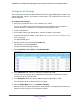
Table Of Contents
- 24-Port Gigabit Smart Managed Pro Switch with PoE+ and 2 SFP Ports Model GS724TPv2
- Contents
- 1. Get Started
- Switch Management Interface Overview
- Change the Default IP Address of the Switch
- Discover a Switch in a Network With a DHCP Server
- Discover a Switch in a Network Without a DHCP Server
- Configure the Network Settings on Your Computer
- Access the Web Browser–Based Management Interface
- About the User Interfaces
- Use a Web Browser to Access the Switch and Log In
- Web Browser–Based Management Interface Device View
- Interface Naming Conventions
- Configure Interface Settings
- Context-Sensitive Help and Access to the Support WebSite
- Register Your Product
- 2. Configure System Information
- 3. Configure Switching
- Configure Port Settings
- Configure Link Aggregation Groups
- Configure VLANs
- Configure a Voice VLAN
- Configure Auto-VoIP
- Configure Spanning Tree Protocol
- Configure Multicast
- View the MFDB Table
- View the MFDB Statistics
- IGMP Snooping Overview
- Configure IGMP Snooping
- Configure IGMP Snooping for Interfaces
- View the IGMP Snooping Table
- Configure IGMP Snooping for VLANs
- Modify IGMP Snooping Settings for a VLAN
- IGMP Snooping Querier Overview
- Configure IGMP Snooping Querier
- Configure IGMP Snooping Querier for VLANs
- Display IGMP Snooping Querier for VLAN Status
- Configure a Static Multicast Group
- Remove a Static Multicast Group
- Configure Multicast Group Membership
- Configure the Multicast Forward All Option
- View and Configure the MAC Address Table
- 4. Configure Quality of Service
- 5. Manage Device Security
- Configure the Management Security Settings
- Configure Management Access
- Configure Port Authentication
- Configure Traffic Control
- Configure Access Control Lists
- Use the ACL Wizard to Create a Simple ACL
- Configure a MAC ACL
- Configure MAC ACL Rules
- Configure MAC Bindings
- View or Delete MAC ACL Bindings in the MAC Binding Table
- Configure an IP ACL
- Configure Rules for a Basic IP ACL
- Configure Rules for an Extended IP ACL
- Configure IP ACL Interface Bindings
- View or Delete IP ACL Bindings in the IP ACL Binding Table
- 6. Monitor the System
- 7. Maintenance
- A. Configuration Examples
- B. Specifications and Default Settings

Configure Switching
94
NETGEAR 24-Port Gigabit Smart Managed Pro Switch with PoE+ and 2 SFP Ports Model GS724TPv2
Note: After you change the autonegotiation mode, the switch might be
inaccessible for a number of seconds while the new settings take effect.
10. In the Speed field, specify the speed value for the selected port.
Possible field values are as follows:
• Auto. All supported speeds. This is the default setting.
• 10Mbps. 10 Mbits/second.
• 100Mbps. 100 Mbits/second.
• 1000Mbps. 1000 Mbits/second.
The delimiter characters for setting different speed values are a comma (,), a period (.)
and a space ( ). For you to set the auto-negotiation speed, the autonegotiation mode must
be set to Enable. The default is Auto.
Note: After you change the speed value, the switch might be inaccessible for
a number of seconds while the new settings take effect.
11. From the Duplex Mode menu, select the duplex mode for the selected port.
Possible values are as follows:
• Auto. Indicates that speed is set by the auto-negotiation process.
• Full. Indicates that the interface supports transmission between the devices in both
directions simultaneously.
• Half. Indicates that the interface supports transmission between the devices in only
one direction at a time.
The default is Auto.
Note: After you change the duplex mode, the switch might be inaccessible for
a number of seconds while the new settings take effect.
12. From the Auto Power Down Mode menu, select whether the auto power down mode of the
Green Ethernet feature is enabled or disabled.
The default is disabled.
13. Use the Link Trap menu to select whether to send a trap when link status changes.
The default is enabled for normal interfaces and disabled for LAG interfaces.
14. Use the Frame Size field to specify the maximum Ethernet frame size the interface supports
or is configured to use, including Ethernet header, CRC, and payload.
The range is 1518 to 9216. The default maximum frame size is 1518.
15. From the Flow Control menu, select to enable or disable IEEE 802.3 flow control.
The default is disabled. The switch does not send pause frames if the port buffers
become full. Flow control helps to prevent data loss when the port cannot keep up with
the number of frames being switched. When flow control is enabled, the switch can send