ProSafe M5300 Switch Web Management User Guide 350 East Plumeria Drive San Jose, CA 95134 USA August 2012 202-10976-01 v1.
ProSafe M5300 Switch © NETGEAR, Inc. All rights reserved No part of this publication may be reproduced, transmitted, transcribed, stored in a retrieval system, or translated into any language in any form or by any means without the written permission of NETGEAR, Inc. NETGEAR, the NETGEAR logo, and Connect with Innovation are trademarks and/or registered trademarks of NETGEAR, Inc. and/or its subsidiaries in the United States and/or other countries. Information is subject to change without notice.
Contents Chapter 1 Getting Started Switch Management Interface . . . . . . . . . . . . . . . . . . . . . . . . . . . . . . . . . . . 9 Web Access . . . . . . . . . . . . . . . . . . . . . . . . . . . . . . . . . . . . . . . . . . . . . . . . . 9 Understanding the User Interfaces. . . . . . . . . . . . . . . . . . . . . . . . . . . . . . . 10 Using the Web Interface . . . . . . . . . . . . . . . . . . . . . . . . . . . . . . . . . . . . . 10 Interface Naming Convention . . . . . . . . . . . . . . . . . . .
ProSafe M5300 Switch NSF . . . . . . . . . . . . . . . . . . . . . . . . . . . . . . . . . . . . . . . . . . . . . . . . . . . . 78 Checkpoint Statistics . . . . . . . . . . . . . . . . . . . . . . . . . . . . . . . . . . . . . . . 80 Stack Template Summary . . . . . . . . . . . . . . . . . . . . . . . . . . . . . . . . . . . 81 Stack Template Configuration . . . . . . . . . . . . . . . . . . . . . . . . . . . . . . . . 82 PoE (M5300-28G-POE+ and M5300-52G-POE+ Only) . . . . . . . . . . . . . . .
ProSafe M5300 Switch LAG Configuration . . . . . . . . . . . . . . . . . . . . . . . . . . . . . . . . . . . . . . . .184 LAG Membership . . . . . . . . . . . . . . . . . . . . . . . . . . . . . . . . . . . . . . . . .186 Chapter 4 Routing Routing Table . . . . . . . . . . . . . . . . . . . . . . . . . . . . . . . . . . . . . . . . . . . . . . 189 Basic . . . . . . . . . . . . . . . . . . . . . . . . . . . . . . . . . . . . . . . . . . . . . . . . . . . 190 Advanced . . . . . . . . . . . . . . . . . . .
ProSafe M5300 Switch Chapter 5 Configuring Quality of Service Class of Service . . . . . . . . . . . . . . . . . . . . . . . . . . . . . . . . . . . . . . . . . . . . 331 Basic. . . . . . . . . . . . . . . . . . . . . . . . . . . . . . . . . . . . . . . . . . . . . . . . . . . 332 Advanced . . . . . . . . . . . . . . . . . . . . . . . . . . . . . . . . . . . . . . . . . . . . . . . 333 Differentiated Services . . . . . . . . . . . . . . . . . . . . . . . . . . . . . . . . . . . . . . . 339 DiffServ Wizard.
ProSafe M5300 Switch Chapter 7 Monitoring the System Ports . . . . . . . . . . . . . . . . . . . . . . . . . . . . . . . . . . . . . . . . . . . . . . . . . . . . . 457 Port Statistics . . . . . . . . . . . . . . . . . . . . . . . . . . . . . . . . . . . . . . . . . . . . 458 Port Detailed Statistics . . . . . . . . . . . . . . . . . . . . . . . . . . . . . . . . . . . . .459 EAP Statistics . . . . . . . . . . . . . . . . . . . . . . . . . . . . . . . . . . . . . . . . . . . . 466 Cable Test . . . . . .
ProSafe M5300 Switch Chapter 9 Help Online Help. . . . . . . . . . . . . . . . . . . . . . . . . . . . . . . . . . . . . . . . . . . . . . . . 501 Support . . . . . . . . . . . . . . . . . . . . . . . . . . . . . . . . . . . . . . . . . . . . . . . . . 501 User Guide . . . . . . . . . . . . . . . . . . . . . . . . . . . . . . . . . . . . . . . . . . . . . . 502 Registration . . . . . . . . . . . . . . . . . . . . . . . . . . . . . . . . . . . . . . . . . . . . . . .
1. 1 Getting Started This chapter provides an overview of starting your NETGEAR ProSafe M5300 Switch and accessing the user interface.
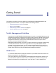
ProSafe M5300 Switch Accessing the switch directly from your Web browser displays the login screen shown below.
ProSafe M5300 Switch Use the following procedures to log on to the Web interface: 1. Open a Web browser and enter the IP address of the switch in the Web browser address field. 2. The default user name is admin, default password is none (no password). Type the user name into the field on the login screen and then click Login. User names and passwords are case sensitive. 3. After the system authenticates you, the System Information page displays.
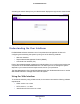
ProSafe M5300 Switch Page Link Configuration Pages Configuration and Monitoring Options The area directly under the feature links and to the right of the page menu displays the configuration information or status for the page you select. On pages that contain configuration options, you can input information into fields or select options from drop-down menus. Each page contains access to the HTML-based help that explains the fields and configuration options for the page.
ProSafe M5300 Switch Device View The Device View is a Java® applet that displays the ports on the switch. This graphic provides an alternate way to navigate to configuration and monitoring options. The graphic also provides information about device ports, current configuration and status, table information, and feature components. The Device View is available from the System Device View page. The port coloring indicates whether a port is currently active.
ProSafe M5300 Switch Device View System LEDs In addition to the port LEDs, the device view provides a representation of the system LEDs on the left side of the front switch panel. Power/Status LED The power LED is a bicolor LED that serves as an indicator of power and diagnostic status. The following indications are given by the following LED states: • A solid green LED indicates that the power is supplied to the switch and operating normally.
ProSafe M5300 Switch Device View Navigation Click the port you want to view or configure to see a menu that displays statistics and configuration options. Click the menu option to access the page that contains the configuration or monitoring options. If you click the graphic, but do not click a specific port, the main menu appears. This menu contains the same option as the navigation tabs at the top of the page.
ProSafe M5300 Switch Help Page Access Every page contains a link to the online help , which contains information to assist in configuring and managing the switch. The online help pages are context sensitive. For example, if the IP Addressing page is open, the help topic for that page displays if you click Help. User-Defined Fields User-defined fields can contain 1 to 159 characters, unless otherwise noted on the configuration Web page.
ProSafe M5300 Switch Interface Naming Convention The ProSafe support physical and logical interfaces. Interfaces are identified by their type and the interface number. The physical ports are gigabit interfaces and are numbered on the front panel. You configure the logical interfaces by using the software. Table 2 describes the naming convention for all interfaces available on the switch. Table 2.
ProSafe M5300 Switch Getting Started 18
2. Configuring System Information 2 Use the features in the System tab to define the switch’s relationship to its environment.
ProSafe M5300 Switch System Information After a successful login, the System Information page displays. Use this page to configure and view general device information. To display the System Information page, click System Management System Information. A screen similar to the following displays.
ProSafe M5300 Switch The System Information provides various statuses: Switch Status To define system information: 1. In the System Name field, enter the name you want to use to identify this switch. You may use up to 255 alphanumeric characters. The factory default is blank. 2. In the System Location field, enter the location of this switch. You may use up to 255 alphanumeric characters. The factory default is blank. 3. In the System Contact field, enter the contact person for this switch.
ProSafe M5300 Switch FAN Status The screen shows the status of the fans in all units. These fans remove the heat generated by the power, CPU, and other chipsets, allowing the chipsets to work normally. Fan status has three possible values: OK, Failure, Not Applicable (NA). The following table describes the Fan Status information. Field Description Unit ID The stack member unit identifier assigned to the switch which the fan belongs to. CPU 1/CPU2 The working status of each CPU fan.
ProSafe M5300 Switch Device Status The screen shows the various inventory information for each device. The following table describes the Device Status information. Field Description Firmware Version The release.version.maintenance.build number of the code currently running on the switch. For example, if the release was 8, the version was 0, the maintenance number was 3, and the build number was 11, the format would be 8.0.3.11.
ProSafe M5300 Switch Switch Statistics Use this page to display the switch statistics. To display the Switch Statistics page, click System > Management > Switch Statistics. A screen similar to the following displays. The following table describes Switch Statistics information. Field Description ifIndex This object indicates the ifIndex of the interface table entry associated with the Processor of this switch.
ProSafe M5300 Switch Field Description Broadcast Packets Received The total number of packets received that were directed to the broadcast address. Note that this does not include multicast packets. Receive Packets Discarded The number of inbound packets which were chosen to be discarded even though no errors had been detected to prevent their being deliverable to a higher-layer protocol. A possible reason for discarding a packet could be to free up buffer space.
ProSafe M5300 Switch System CPU Status Use this page to display system CPU status and utilization information. To display the System Resource page, click System > Management > System CPU Status. A screen similar to the following displays. System CPU Status The following table describes CPU Memory Status information. Field Description Total System Memory The total memory of the switch in KBytes. Available Memory The available memory space for the switch in KBytes.
ProSafe M5300 Switch Slot Information Use this page to view information about the cards installed in the switch’s slots. This page also provides information about the cards and switches that are compatible with the device. To display the Switch Statistics page, click System > Management > Slot Information. A screen similar to the following displays. Slot Summary The following table describes information in the Slot Summary table. Field Description Slot The slot number.
ProSafe M5300 Switch Field Description Card Power Down If the value is True, the Power State can be administratively enabled or disabled. If the value is False, the Power State cannot be configured. Card Pluggable If the value is True, the card can be administratively enabled or disabled. If the value is False, the Administrative State cannot be configured. Supported Card The following table describes information in the Supported Card table.
ProSafe M5300 Switch Loopback Interface Use this page to create, configure, and remove Loopback interfaces. A loopback interface is a logical interface that is considered to be always up. To display the Loopback Interface page, click System > Management > Loopback Interface. A screen similar to the following displays. To configure a loopback interface: 1. In the Loopback Interface Type field select whether the interface is an IPv4 or IPv6 loopback interface.
ProSafe M5300 Switch Network Interface From the Network Interface link, you can access the following pages: • IPv4 Network Configuration on page 30 • IPv6 Network Interface Configuration on page 32 • IPv6 Network Interface Neighbor Table on page 33 IPv4 Network Configuration To display the IPv4 Network Configuration page, click System > Management > Network Interface > IPv4 Network Configuration. A screen similar to the following displays.
ProSafe M5300 Switch Once you have established in-band connectivity, you can change the IP information using any of the following: • Terminal interface via the EIA-232 port • Terminal interface via telnet • SNMP-based management • Web-based management To configure an IPv4 network interface: 1. Use Current Network Configuration Protocol to specify how the device acquires network information on the network interface: • None – The switch does not attempt to acquire network information dynamically.
ProSafe M5300 Switch 8. Use DHCP Vendor Class Identifier String to specify the text string to add to DHCP requests as option 60, the VCI option. 9. Use Management VLAN ID to specify the management VLAN ID of the switch. It may be configured to any value in the range of 1 - 4093. Some network administrators use a management VLAN to isolate system management traffic from end-user data traffic. 10. Click APPLY to update the network interface with the specified values. 11. Click CANCEL to abandon the changes.
ProSafe M5300 Switch To configure an IPv6 network interface: 1. Use Admin Mode to enable or disable the IPv6 network interface on the switch. The default value is enable. 2. Use IPv6 Address Auto Configuration Mode to set the IPv6 address for the IPv6 network interface in auto configuration mode if this option is enabled. The default value is disable. Auto configuration can be enabled only when IPv6 Auto config or DHCPv6 are not enabled on any of the management interfaces. 3.
ProSafe M5300 Switch Field Description IsRtr True(1) if the neighbor machine is a router, false(2) otherwise. Neighbor State The state of the neighboring switch: • reachable(1) - The neighbor is reachable by this switch. • stale(2) - Information about the neighbor is scheduled for deletion. • delay(3) - No information has been received from neighbor during delay period. • probe(4) - Switch is attempting to probe for this neighbor. • unknown(6) - Unknown status.
ProSafe M5300 Switch The device can poll Unicast server types for the server time. Polling for Unicast information is used for polling a server for which the IP address is known. SNTP servers that have been configured on the device are the only ones that are polled for synchronization information. T1 through T4 are used to determine server time. This is the preferred method for synchronizing device time because it is the most secure method.
ProSafe M5300 Switch SNTP Global Configuration SNTP stands for Simple Network Time Protocol. As its name suggests, it is a less complicated version of Network Time Protocol, which is a system for synchronizing the clocks of networked computer systems, primarily when data transfer is handled via the Internet. 1. Use Client Mode to specify the mode of operation of SNTP Client. An SNTP client may operate in one of the following modes. • Disable - SNTP is not operational.
ProSafe M5300 Switch SNTP Global Status The following table displays SNTP Global Status information. Field Description Version Specifies the SNTP Version the client supports. Supported Mode Specifies the SNTP modes the client supports. Multiple modes may be supported by a client. Last Update Time Specifies the local date and time (UTC) the SNTP client last updated the system clock.
ProSafe M5300 Switch Field Description Unicast Server Current Entries Specifies the number of current valid unicast server entries configured for this client. Broadcast Count Specifies the number of unsolicited broadcast SNTP messages that have been received and processed by the SNTP client since last reboot. SNTP Server Configuration Use the SNTP Server Configuration page to view and modify information for adding and modifying Simple Network Time Protocol SNTP servers.
ProSafe M5300 Switch 2. Click ADD. 3. Repeat the previous steps to add additional SNTP servers. You can configure up to three SNTP servers. 4. To removing an SNTP server, select the check box next to the configured server to remove, and then click DELETE. The entry is removed, and the device is updated. 5. To change the settings for an existing SNTP server, select the check box next to the configured server and enter new values in the available fields, and then click APPLY.
ProSafe M5300 Switch DNS You can use these pages to configure information about DNS servers the network uses and how the switch operates as a DNS client. DNS Configuration Use this page to configure global DNS settings and DNS server information. To access this page, click System Management DNS DNS Configuration. To configure the global DNS settings: 1. Specify whether to enable or disable the administrative status of the DNS Client.
ProSafe M5300 Switch 7. Click CANCEL to cancel the configuration on the screen and reset the data on the screen to the latest value of the switch. 8. Click APPLY to send the updated configuration to the switch. Configuration changes take effect immediately. DNS Server Configuration The following table displays DNS Server Configuration information. Field Description Serial No The sequence number of the DNS server. Preference Shows the preference of the DNS Server.
ProSafe M5300 Switch The Dynamic Host Mapping table shows host name-to-IP address entries that the switch has learned. The following table describes the dynamic host fields. Field Description Host Lists the host name you assign to the specified IP address. Total Amount of time since the dynamic entry was first added to the table. Elapsed Amount of time since the dynamic entry was last updated. Type The type of the dynamic entry. Addresses Lists the IP address associated with the host name.
ProSafe M5300 Switch The following table displays Summary information, which describes the maximum resources each template supports for various features.. Field Description SDM Template Identifies the Template. The possible values are: • Dual IPv4 and IPv6 • IPv4-routing Default • IPv4 Data Center ARP Entries The maximum number of entries in the IPv4 Address Resolution Protocol (ARP) cache for routing interfaces. IPv4 Unicast Routes The maximum number of IPv4 unicast forwarding table entries.
ProSafe M5300 Switch The following table describes the non-configurable fields on the License Key page. Field Description License Date The date the license is purchased. License Copy The number of licenses that exist on the switch. License Status Indicates whether the license is active or inactive. If a license is inactive, a license should be purchased and downloaded to the switch. The license is not activated until the switch reboots. Description A description of the license key status.
ProSafe M5300 Switch Services From the Services link, you can access the following pages: • DHCP Server on page 45 • DHCP Relay on page 53 • DHCP L2 Relay on page 54 • UDP Relay on page 57 • DHCPv6 Server on page 59 • DHCPv6 Relay on page 66 DHCP Server DHCP is generally used between clients and servers for the purpose of assigning IP addresses, gateways, and other network settings such as DNS and SNTP server information.
ProSafe M5300 Switch To enable or disable DHCP service: 1. Use Admin Mode to specify whether the DHCP Service is to be Enabled or Disabled. Default value is Disable. 2. Use Ping Packet Count to specify the number of packets a server sends to a Pool address to check for duplication as part of a ping operation. Default value is 2. Valid Range is (0, 2 to 10). Setting the value to 0 will disable the function. 3.
ProSafe M5300 Switch DHCP Pool Configuration To display the DHCP Pool Configuration page, click System > Services > DHCP Server> DHCP Pool Configuration. A screen similar to the following displays. To configure a DHCP pool: 1.
ProSafe M5300 Switch Field Description Type of Binding Specifies the type of binding for the pool. • Unallocated • Dynamic • Manual Network Address Specifies the subnet address for a DHCP address of a dynamic pool. Network Mask Specifies the subnet number for a DHCP address of a dynamic pool. Either Network Mask or Prefix Length can be configured to specify the subnet mask but not both. Network Prefix Length Specifies the subnet number for a DHCP address of a dynamic pool.
ProSafe M5300 Switch Field Description DNS Server Addresses Specifies the list of DNS Server Addresses for the pool. The user may specify up to 8 DNS Server Addresses in order of preference. NetBIOS Name Server Addresses Specifies the list of NetBIOS Name Server Addresses for the pool. The user may specify up to 8 NetBIOS Name Server Addresses in order of preference.
ProSafe M5300 Switch 3. Use Option Type to specify the Option Type against the Option Code configured for the selected pool: • ASCII • Hex • IP Address 4. Option Value specifies the Value against the Option Code configured for the selected pool. 5. Click ADD to add a new Option Code for the selected pool. 6. Click DELETE to delete the Option Code for the selected pool. DHCP Server Statistics To display the DHCP Server Statistics page, click System > Services > DHCP Server> DHCP Server Statistics.
ProSafe M5300 Switch Field Description DHCPDECLINE Specifies the number of DHCPDECLINE messages received by the DHCP Server. DHCPRELEASE Specifies the number of DHCPRELEASE messages received by the DHCP Server. DHCPINFORM Specifies the number of DHCPINFORM messages received by the DHCP Server. DHCPOFFER Specifies the number of DHCPOFFER messages sent by the DHCP Server. DHCPACK Specifies the number of DHCPACK messages sent by the DHCP Server.
ProSafe M5300 Switch DHCP Conflicts Information To display the DHCP Conflicts Information page, click System > Services > DHCP Server> DHCP Conflicts Information. A screen similar to the following displays. 1. Choose: • All Address Conflicts to specify all address conflicts to be deleted. • Specific Address Conflict to specify a specific dynamic binding to be deleted. The following table describes the DHCP Conflicts Information fields.
ProSafe M5300 Switch DHCP Relay If the switch is functioning as a Layer 3 device, the Layer 3 DHCP Relay Agent can relay DHCP messages between DHCP clients and DHCP servers that are located in different IP subnets. To display the DHCP Relay page, click System > Services> DHCP Relay. A screen similar to the following displays. DHCP Relay Configuration To configure the DHCP Relay information: 1. Use Maximum Hop Count to enter the maximum number of hops a client request can take before being discarded.
ProSafe M5300 Switch DHCP Relay Status The following table describes the DHCP Relay Status fields. Field Description Requests Received The total number of DHCP requests received from all clients since the last time the switch was reset. Requests Relayed The total number of DHCP requests forwarded to the server since the last time the switch was reset. Packets Discarded The total number of DHCP packets discarded by this Relay Agent since the last time the switch was reset.
ProSafe M5300 Switch To configure the DHCP L2 Relay VLAN information: 1. VLAN ID shows the VLAN ID configured on the switch. 2. Use Admin Mode to enable or disable the DHCP L2 Relay on the selected VLAN. 3. Use Circuit ID Mode to enable or disable the Circuit ID suboption of DHCP Option-82. 4. Use Remote ID String to specify the Remote ID when Remote ID mode is enabled.
ProSafe M5300 Switch DHCP L2 Relay Interface Statistics To display the DHCP L2 Relay Interface Statistics page, click System > Services > DHCP L2 Relay> DHCP L2 Relay Interface Statistics. A screen similar to the following displays. The following table describes the DHCP L2 Relay Interface Statistics fields. Field Description Interface Shows the interface from which the DHCP message is received.
ProSafe M5300 Switch UDP Relay The UDP Relay feature provides the ability for a router to forward configured UDP broadcast packets to a particular IP address. This allows applications to reach servers on non-local subnets. This is possible even when the application is designed to assume a server is always on a local subnet or when the application uses broadcast packets to reach the server (with the limited broadcast address 255.255.255.255, or a network directed broadcast address).
ProSafe M5300 Switch • rip - Relay RIP (UDP port 520) packets • tacacs - Relay TACACS (UDP port 49) packet • tftp - Relay TFTP (UDP port 69) packets • time - Relay time service (UDP port 37) packets • Other - If this option is selected, the UDP Port Other Value is enabled. This option permits a user to enter their own UDP port in UDP Port Other Value. 4. Use UDP Port Other Value to specify a UDP Destination Port that lies between 0 and 65535. 5.
ProSafe M5300 Switch • ntp - Relay network time protocol (UDP port 123) packets. • pim-auto-rp - Relay PIM auto RP (UDP port 496) packets. • rip - Relay RIP (UDP port 520) packets • tacacs - Relay TACACS (UDP port 49) packet • tftp - Relay TFTP (UDP port 69) packets • time - Relay time service (UDP port 37) packets • Other - If this option is selected, the UDP Port Other Value is enabled. This option permits the user to enter their own UDP port in UDP Port Other Value. 4.
ProSafe M5300 Switch DHCPv6 Server Configuration To display the DHCP Server Configuration page, click System > Services > DHCPv6 Server> DHCP Server Configuration. A screen similar to the following displays. To configure global DHCPv6 server settings: 1. Use Admin Mode to specify whether the DHCPv6 Service is to be Enabled or Disabled. Default value is Disable. 2. In the DHCPv6 Server DUID field, view the client identifier used by the DHCPv6 client (if enabled) when sending messages to the DHCPv6 server..
ProSafe M5300 Switch Configuring System Information 61
ProSafe M5300 Switch To configure a DHCPv6 Pool: 1. From the Pool Name field, select Create and enter name for the Pool to be created. To modify information for an existing DHCPv6 pool, select the name of the pool to configure. 2. If you are configuring a new DHCPv6 pool, specify a unique name for the pool in the Pool Name field. 3. Click the DNS Server Addresses field to expand the field, and enter the IPv6 address for one or more DNS servers. 4.
ProSafe M5300 Switch 5. In the Valid Lifetime field, specify the valid lifetime, in seconds, for the delegated prefix. The values allowed are between 0 to 4294967295. 6. In the Prefer Lifetime field, specify the preferred lifetime, in seconds, for the delegated prefix. The values allowed are between 0 to 4294967295. 7. Click ADD to add a new delegated prefix for the selected pool. 8. Select the check box associated with a prefix delegation and click DELETE to remove the delegated prefix. 9.
ProSafe M5300 Switch 5. In the Preferences field, specify the preference value used by clients to determine preference between multiple DHCPv6 servers. The values allowed are between 0 to 4294967295. The default value is 0. 6. Click APPLY to send the updated configuration to the switch. Configuration changes take effect immediately. 7. Click CANCEL to cancel the configuration on the screen and reset the data on the screen to the latest value of the switch.
ProSafe M5300 Switch DHCPv6 Server Statistics To display the DHCP Server Statistics page, click System > Services > DHCPv6 Server> DHCPv6 Server Statistics. A screen similar to the following displays. The following table describes the DHCPv6 Server Statistics fields. Field Description Interface Select the interface with the statistics to view. Messages Received Specifies the aggregate of all interface level statistics for received messages.
ProSafe M5300 Switch Field Description DHCPv6 Release Packets Received Specifies the number of Releases. DHCPv6 Decline Packets Received Specifies the number of Declines. DHCPv6 Inform Packets Received Specifies the number of Informs. DHCPv6 Relay-forward Packets Received Specifies the number of Relay forwards. DHCPv6 Relay-reply Packets Received Specifies the number of Relay Replies. DHCPv6 Malformed Packets Received Specifies the number of Malformed Packets.
ProSafe M5300 Switch To configure the DHCPv6 Relay information for one or more interfaces: 1. Select the check box associated with each interface to configure, or select the check box in the heading row to apply the same configuration to all interfaces. 2. In the Admin Mode field, specify the DHCPv6 mode to configure DHCPv6 Relay functionality. DHCPv6 server and DHCPv6 relay functions are mutually exclusive. 3. In the Relay Interface field, specify an interface to reach a relay server. 4.
ProSafe M5300 Switch Stacking A stackable switch is a switch that is fully functional operating as a stand-alone unit but can also be set-up to operate together with up to seven other switches. This group of switches shows the characteristics of a single switch while having the port capacity of the sum of the combined switches.
ProSafe M5300 Switch • Single IP address management through a web browser, the CLI, or SNMP. • Master-slave configuration. • The master retains configuration for entire stack. • Automatic detection of new members, with synchronization of firmware (upgrade or downgrade as needed). • Configuration updates across the stack through a single operation. • Automatic master fail-over. Fully resilient stack with chain and ring topology. • Hot swapping (insertion and removal) of stack members.
ProSafe M5300 Switch Stack Master Election All stack members are eligible stack masters. If the stack master becomes unavailable, the remaining stack members participate in electing a new stack master from among themselves.
ProSafe M5300 Switch Nonstop Forwarding Nonstop forwarding (NSF) allows the forwarding plane of stack units to continue to forward packets while the control and management planes restart as a result of a power failure, hardware failure, or software fault on the management unit. A nonstop forwarding failover can also be manually initiated by clicking the Initiate Failover button on the NSF Summary page.
ProSafe M5300 Switch Stack Configuration From this page, you can preconfigure stack members before adding them to the stack, change the unit number assigned to a stack member, and to select a new stack master or give management preference to one or more units. If you change the unit ID on a stack member, the member reloads. A stack move causes all routes and layer 2 addresses to be lost. The administrator is prompted to confirm the management move.
ProSafe M5300 Switch To change the settings for an existing stack member: 1. Select the check box next to the stack member to configure. 2. If desired, specify a new unit ID for the stack member in the Change to Switch ID field. The renumbering process causes the unit to reload. 3. Specify the switch type, priority, or management status from the available fields. 4. Click Apply to save the changes to the stack member.
ProSafe M5300 Switch The following table describes the Basic Stack Status fields. Field Description Unit ID The unit ID of the specific switch. Switch Description The description for the unit can be configured by the user. Serial Number The unique box serial number for this switch. Uptime The displays the relative time since the last reboot of the switch. Preconfigured Model Identifier This field displays the model type assigned by the device manufacturer to identify the device.
ProSafe M5300 Switch To configure the mode of the stack ports: 1. Select the check box associated with the unit and port to configure: 2. From the Configured Stack Mode field, select the operating mode: • Stack. The port connects to the stack port on another stack member. This is the default value. • Ethernet. The port operates as a standard switch port that receives and transmits network traffic 3. Click Apply to apply the new settings to the system. 4.
ProSafe M5300 Switch Field Description Link Status Displays the link status (UP/DOWN) of the port. Link Speed (Gbps) Displays the maximum speed of the stacking port. Transmit Data Rate (Mbps) Displays the approximate transmit rate on the stacking port. Transmit Error Rate Displays the number of errors in transmit packets per second. Total Transmit Errors Displays the total number of errors in transmit packets since boot. The counter may wrap.
ProSafe M5300 Switch Stack Firmware Synchronization To display the stack firmware synchronization configurations from the Stack Firmware Synchronization page, click System Stacking Advanced Stack Firmware Synchronization. A screen similar to the following is displayed. To configure the Stack Firmware Synchronization features: 1. Specify whether Stack Firmware Auto Upgrade is enabled or disabled.
ProSafe M5300 Switch NSF Use the NSF Summary page to enable nonstop forwarding feature on the stack, view operational status information, and to initiate a warm restart of the management unit. When nonstop forwarding is enabled, if the management unit of a stack fails, the backup unit takes over as the master without clearing the hardware tables of any of the surviving units. Data traffic continues to be forwarded in hardware while the management functions initialize on the backup unit.
ProSafe M5300 Switch 4. Click CANCEL to abandon the changes. 5. Click RESET to redisplay the page with the latest status values from the switch. The NSF Summary page includes the following non-configurable information: Field Description Operation Status Indicates whether NSF is operational on the stack, which may differ from the Admin Status setting. If a unit that does not support NSF is connected to the stack, then NSF is disabled on all stack members.
ProSafe M5300 Switch Checkpoint Statistics Use the Checkpoint Statistics page to display information about the protocol and routing data that the management unit shares with the backup unit. To display the Checkpoint Statistics page, click System Stacking Advanced NSF > Checkpoint Statistics. A screen similar to the following is displayed.
ProSafe M5300 Switch The following table describes the fields on the Checkpoint Statistics page: Field Description Messages Checkpointed The number of messages sent from master unit to backup unit. Bytes Checkpointed How much data has been sent from master unit to the backup unit. Time Since Counters Cleared The amount of time since the counters have been reset. Message Rate Interval The number of seconds between measurements.
ProSafe M5300 Switch PoE (M5300-28G-POE+ and M5300-52G-POE+ Only) Copper Ethernet ports 1–24 on the M5300-28G-POE+ and copper Ethernet ports 1–48 on the M5300-52G-POE+ are PoE+ (IEEE 802.3at) compliant ports. Each port is capable of delivering up to 30W of reliable, uninterrupted power to connected PoE-powered devices (PD). The GS728TPS can provide a total of 192W of power to all connected devices. The GS752TPS can provide a total of 384W of power to all connected devices.
ProSafe M5300 Switch Basic PoE Configuration Use the PoE Configuration page to view global PoE power information and to configure PoE settings. To display the Basic PoE Configuration page, click System > Services > PoE > Basic > PoE Configuration. A screen similar to the following displays. To configure PoE trap settings: 1. If you are managing a stack of switches, select the ID of the stack member to configure from the Unit menu. 2.
ProSafe M5300 Switch The PoE Configuration page also provides the following information: Field Description Firmware Version Version of the PoE controller's FW image. Power Status Indicates whether the PoE capability is on or off. Nominal Power Indicates the nominal amount of power the switch can provide to all ports. Threshold Power Shows the amount of power the system can consume before the system will not provide power to an additional port.
ProSafe M5300 Switch To configure PoE Port settings: 1. Select the check box next to the port to configure. Select multiple check boxes to apply the same settings to each selected port. Select the check box in the heading row to apply the same settings to all ports. 2. Configure or view the settings: • Admin Mode. Enable or disable the ability of the port to deliver power. • High Power. Indicates whether the port supports High Power Mode. • Max Power.
ProSafe M5300 Switch • Class. View the class of the PD connected to the port. The class defines the range of power a PD is drawing from the system. The class is defined as: • 0: 0.44–12.95W • 1: 0.44–3.83W • 2: 3.84–6.48W • 3: 6.49–12.95W • 4: 12.95–25.50W (802.3at Type 2 devices only) • Timer Schedule. Select the timer schedule to use for the port. By default, no timer schedules are configured. To create a timer schedule, use the Timer Schedule Global Configuration page. • Output Voltage.
ProSafe M5300 Switch SNMP From SNMP link under the System tab, you can configure SNMP settings for SNMP V1/V2 and SNMPv3. From the SNMP link, you can access the following pages: • SNMPV1/V2 on page 87 • SNMP V3 User Configuration on page 92 SNMPV1/V2 The pages under the SNMPV1/V2 menu allow you to configure SNMP community information, traps, and trap flags.
ProSafe M5300 Switch To configure SNMPv1/v2 communities: 1. Use Community Name to reconfigure an existing community, or to create a new one. Use this pull-down menu to select one of the existing community names, or select 'Create' to add a new one. A valid entry is a case-sensitive string of up to 16 characters. 2. Client Address - Taken together, the Client Address and Client IP Mask denote a range of IP addresses from which SNMP clients may use that community to access this device.
ProSafe M5300 Switch Trap Configuration This page displays an entry for every active Trap Receiver. To access this page, click System SNMP SNMP V1/V2 Trap Configuration. To configure SNMPv1/v2 traps: 1. To add a host that will receive SNMP traps, enter trap configuration information in the available fields described below, and then click ADD. a. Community Name - Enter the community string for the SNMP trap packet to be sent to the trap manager. This may be up to 16 characters and is case sensitive.
ProSafe M5300 Switch Trap Flags Use the Trap Flags page to enable or disable traps. When the condition identified by an active trap is encountered by the switch, a trap message is sent to any enabled SNMP Trap Receivers, and a message is written to the trap log. To access the Trap Flags page, click System SNMP SNMP V1/V2 Trap Flags. The following screen shows some, but not all, of the SNMPv1/v2 trap flags. To configure the trap flags: 1.
ProSafe M5300 Switch 5. Use ACL to enable or disable activation of ACL traps by selecting the corresponding radio button. The factory default is disabled. 6. Use PoE to enable or disable activation of PoE traps by selecting the corresponding radio button. The factory default is enabled. Indicates whether PoE traps will be sent. 7. Use DVMRP to enable or disable activation of DVMRP traps by selecting the corresponding radio button. The factory default is disabled. 8.
ProSafe M5300 Switch SNMP V3 User Configuration To access this page, click System SNMP SNMP V3 User Configuration. A screen similar to the following displays. To configure SNMPv3 settings for the user account: 1. Use User Name to specify the user account to be configured. 2. SNMP v3 Access Mode - Indicates the SNMPv3 access privileges for the user account. The admin account always has 'Read/Write' access, and all other accounts have 'Read Only' access. 3.
ProSafe M5300 Switch LLDP The IEEE 802.1AB-defined standard, Link Layer Discovery Protocol (LLDP), allows stations on an 802 LAN to advertise major capabilities and physical descriptions. This information is viewed by a network manager to identify system topology and detect bad configurations on the LAN. From the LLDP link, you can access the following pages: • LLDP on page 93 • LLDP-MED on page 100 LLDP is a one-way protocol; there are no request/response sequences.
ProSafe M5300 Switch LLDP Global Configuration Use the LLDP Global Configuration page to specify LLDP parameters that are applied to the switch. To display this page, click System LLDP Global Configuration. A screen similar to the following displays. To configure global LLDP settings: 1. Use Transmit Interval to specify the interval in seconds to transmit LLDP frames. The range is from 5 to 32768 secs. Default value is 30 seconds. 2.
ProSafe M5300 Switch LLDP Interface Configuration To display this page, click System LLDP Interface Configuration. A screen similar to the following displays. 1. Use Port to specify the list of ports on which LLDP - 802.1AB can be configured. 2. Link Status indicates whether the Link is up or down. 3. Use Transmit to specify the LLDP - 802.1AB transmit mode for the selected interface. 4. Use Receive to specify the LLDP - 802.1AB receive mode for the selected interface. 5.
ProSafe M5300 Switch LLDP Statistics To display this page, click System LLDP Statistics. A screen similar to the following displays. The following table describes the LLDP Statistics fields. Field Description Last Update Specifies the time when an entry was created, modified or deleted in the tables associated with the remote system.
ProSafe M5300 Switch Field Description Receive Total Specifies the number of valid LLDP frames received by this LLDP agent on the corresponding port, while the LLDP agent is enabled. Discards Specifies the number of LLDP TLVs discarded for any reason by the LLDP agent on the corresponding port. Errors Specifies the number of invalid LLDP frames received by the LLDP agent on the corresponding port, while the LLDP agent is enabled.
ProSafe M5300 Switch To view LLDP information transmitted by an interface, select the desired interface from the Interface menu. The following table describes the LLDP Local Device Information fields. Field Description Chassis ID Subtype Specifies the string that describes the source of the chassis identifier. Chassis ID Specifies the string value used to identify the chassis component associated with the local system.
ProSafe M5300 Switch LLDP Remote Device Information This page displays information on remote devices connected to the port. To display this page, click System LLDP Remote Device Information. A screen similar to the following displays. To view LLDP information received by an interface, select the desired interface from the Interface menu. The following table describes the LLDP Remote Device Information fields. Field Description Chassis ID Subtype Specifies the source of the chassis identifier.
ProSafe M5300 Switch Field Description Time to Live Specifies the Time To Live value in seconds of the received remote entry. Management Address • • Management Address - Specifies the advertised management address of the remote system. Type - Specifies the type of the management address. LLDP Remote Device Inventory To display this page, click System LLDP LLDP Remote Device Inventory. A screen similar to the following displays.
ProSafe M5300 Switch LLDP-MED Global Configuration Use the LLDP-MED Global Configuration page to specify LLDP-MED parameters that are applied to the switch. To display this page, click System LLDP LLDP-MED Global Configuration. A screen similar to the following displays. To configure global LLDP-MED settings: 1. Use Fast Start Repeat Count to specify the number of LLDP PDUs that will be transmitted when the protocol is enabled. The range is from (1 to 10). Default value of fast repeat count is 3. 2.
ProSafe M5300 Switch LLDP-MED Interface Configuration To display this page, click System LLDP LLDP-MED Interface Configuration. A screen similar to the following displays. To configure LLDP-MED interface settings: 1. To configure LLDP-MED settings on one or more interfaces, select the check box associated with each interface to configure, or select the check box in the heading row to apply the same settings to all interfaces. 2.
ProSafe M5300 Switch LLDP-MED Local Device Information To display this page, click System LLDP LLDP-MED Local Device Information. A screen similar to the following displays.
ProSafe M5300 Switch To view LLDP-MED information transmitted by an interface, select the desired interface from the Interface menu. The following table describes the LLDP-MED Local Device Information fields. Field Description Network Policy Information: Specifies if network policy TLV is present in the LLDP frames. Media Application Type Specifies the application type.
ProSafe M5300 Switch LLDP-MED Remote Device Information To display this page, click System LLDP LLDP-MED Remote Device Information. A screen similar to the following displays. To view LLDP-MED information received by an interface, select the desired interface from the Interface menu.
ProSafe M5300 Switch The following table describes the LLDP-MED Remote Device Information fields. Field Description Remote ID Specifies the remote client identifier assigned to the remote system. Capability Information: Specifies the supported and enabled capabilities that was received in MED TLV on this port. Supported Capabilities Specifies supported capabilities that was received in MED TLV on this port.
ProSafe M5300 Switch Field Description Inventory Information: Specifies if inventory TLV is received in LLDP frames on this port. Hardware Revision Specifies hardware version of the remote device. Firmware Revision Specifies Firmware version of the remote device. Software Revision Specifies Software version of the remote device. Serial Number Specifies serial number of the remote device. Manufacturer Name Specifies manufacturers name of the remote device.
ProSafe M5300 Switch LLDP-MED Remote Device Inventory To display this page, click System LLDP LLDP-MED Remote Device Inventory. A screen similar to the following displays. The following table describes the LLDP-MED Remote Device Inventory fields. Field Definition Port Specifies the list of all the ports on which LLDP-MED is enabled. Management Address Specifies the advertised management address of the remote system. MAC Address Specifies the MAC Address associated with the remote system.
ProSafe M5300 Switch ISDP The Industry Standard Discovery Protocol (ISDP) is a proprietary Layer 2 network protocol which inter-operates with Cisco® devices running the Cisco Discovery Protocol (CDP). ISDP is used to share information between neighboring devices. ISDP software participates in the CDP protocol and is able to both discover and be discovered by other CDP supporting devices.
ProSafe M5300 Switch The following table describes the ISDP Basic Global Configuration fields. Field Description Neighbors table last time changed The amount of time that has passed since the ISDP neighbor table was updated. Device ID The Device ID advertised by this device. The format of this Device ID is characterized by the value of Device ID Format object. Device ID format capability Indicates the Device ID format capability of the device.
ProSafe M5300 Switch ISDP Interface Configuration To display this page, click System ISDP Advanced Interface Configuration. A screen similar to the following displays. To configure per-interface ISDP settings: 1. To configure ISDP settings on one or more interfaces, select the check box associated with each interface to configure, or select the check box in the heading row to apply the same settings to all interfaces. 2. Use Admin Mode to enable or disable ISDP on the port.
ProSafe M5300 Switch The following table describes the ISDP Neighbor fields. Field Description Device ID The device ID of the ISDP neighbor. Interface The interface on which the neighbor is discovered. Address Displays the address of the neighbor. Capability Displays the capability of the neighbor. These are supported: • Router • Trans Bridge • Source Route • Switch • Host • IGMP • Repeater Platform Display the model type of the neighbor. (0 to 32) Port ID Display the port ID on the neighbor.
ProSafe M5300 Switch ISDP Statistics Use the ISDP Statistics page to view information about the ISDP packets sent and received by the switch. To display this page, click System ISDP Advanced Statistics. A screen similar to the following displays. The following table describes the ISDP Statistics fields. Field Description ISDP Packets Received Displays the ISDP packets received including ISDPv1 and ISDPv2 packets.
ProSafe M5300 Switch Timer Schedule The Timer Schedule feature allows you to configure time ranges to use in time-based access control list (ACL) rules. For switches that support PoE+, timers can also control when power can and cannot be delivered to the port. Time-based ACLs allow one or more rules within an ACL to be based on a periodic or absolute time. Each ACL rule within an ACL except for the implicit deny all rule can be configured to be active and operational only during a specific time period.
ProSafe M5300 Switch 3. Click ADD to add the new timer schedule with a specified name. The configuration changes take effect immediately. 4. To remove a configured timer, select the entry to remove and click DELETE. The configuration changes take effect immediately. 5. Click CANCEL to cancel the configuration on the screen and reset the data on the screen to the latest values. 6. To change the administrative mode, select the desired option and click APPLY. The configuration changes take effect immediately.
ProSafe M5300 Switch Periodic Timer Absolute Timer To configure a timer schedule: 1. Select the name of the schedule created on the Timer Global Configuration page. 2. Specify the type of timer to configure: • Absolute. The timer occurs once. • Periodic. The timer occurs periodically at regular intervals. The fields available for the timer schedule configuration depend on the selected timer type. 3.
ProSafe M5300 Switch 6. Use the Recurrence Pattern to show with what period the event will repeat. These fields are available only if the scheduler type is periodic. If recurrence is not needed (a timer schedule should be triggered just once), then set 'Date Stop' as equal to 'Date Start'.
ProSafe M5300 Switch Configuring System Information 118
3. Configuring Switching Information 3 Use the features in the Switching tab to define Layer 2 features.
ProSafe M5300 Switch Basic From the Basic link, you can access the following pages: • VLAN Configuration on page 120 VLAN Configuration Use the VLAN Configuration page to define VLAN groups stored in the VLAN membership table. Each switch in the ProSafe family supports up to 1024 VLANs. Two VLANs are created by default: • VLAN 1 is the default VLAN of which all ports are members. • VLAN 2 is the default VLAN for the Auto VoIP feature.
ProSafe M5300 Switch • All ports are configured with Ingress Filtering disabled. • All ports are configured to transmit only untagged frames. • GVRP is disabled on all ports and all dynamic entries are cleared. Internal VLAN Configuration This section displays the allocation base and the allocation mode of internal VLAN. The internal VLAN is reserved by port-based routing interface and invisible to the end user.
ProSafe M5300 Switch Advanced From the Advanced link, you can access the following pages: • VLAN Configuration on page 120 • VLAN Membership on page 122 • VLAN Status on page 124 • Port PVID Configuration on page 125 • MAC Based VLAN on page 126 • Protocol Based VLAN Group Configuration on page 127 • Protocol Based VLAN Group Membership on page 128 • IP Subnet Based VLAN on page 129 • Port DVLAN Configuration on page 130 • Voice VLAN Configuration on page 131 • GARP Switch Configuratio
ProSafe M5300 Switch To configure VLAN membership: 1. Use VLAN ID to select the VLAN ID for which you want to display or configure data. 2. Use Group Operation to select all the ports and configure them: • Untag All - Select all the ports on which all frames transmitted for this VLAN will be untagged. All the ports will be included in the VLAN. • Tag All - Select the ports on which all frames transmitted for this VLAN will be tagged. All the ports will be included in the VLAN.
ProSafe M5300 Switch VLAN Status Use this page to display the status of all currently configured VLANs. To display the VLAN Status page, click Switching VLAN Advanced VLAN Status. Field Definition VLAN ID The VLAN Identifier (VID) of the VLAN. The range of the VLAN ID is 1 to 4093. VLAN Name The name of the VLAN. VLAN ID 1 is always named `Default`.
ProSafe M5300 Switch Port PVID Configuration The Port PVID Configuration screen lets you assign a port VLAN ID (PVID) to an interface. There are certain requirements for a PVID: • All ports must have a defined PVID. • If no other value is specified, the default VLAN PVID is used. • If you want to change the port’s default PVID, you must first create a VLAN that includes the port as a member. • Use the Port VLAN ID (PVID) Configuration page to configure a virtual LAN on a port.
ProSafe M5300 Switch 6. Ingress Filtering: • When enabled, the frame is discarded if this port is not a member of the VLAN with which this frame is associated. In a tagged frame, the VLAN is identified by the VLAN ID in the tag. In an untagged frame, the VLAN is the Port VLAN ID specified for the port that received this frame. • When disabled, all frames are forwarded in accordance with the 802.1Q VLAN bridge specification. The factory default is disabled.
ProSafe M5300 Switch Protocol Based VLAN Group Configuration You can use a protocol based VLAN to define filtering criteria for untagged packets. By default, if you do not configure any port- (IEEE 802.1Q) or protocol based VLANs, untagged packets will be assigned to VLAN 1. You can override this behavior by defining either port-based VLANs or protocol based VLANs, or both. Tagged packets are always handled according to the IEEE 802.1Q standard, and are not included in protocol based VLANs.
ProSafe M5300 Switch 4. Use VLAN ID to select the VLAN ID. It can be any number in the range of 1 to 4093. All the ports in the group will assign this VLAN ID to untagged packets received for the protocols you included in this group. 5. Click ADD to add a new Protocol Based VLAN group to the switch. 6. Click DELETE to remove the Protocol Based VLAN group identified by the value in the Group ID field. Field Description Ports Identifies all the member ports which belong to the group.
ProSafe M5300 Switch IP Subnet Based VLAN IP Subnet to VLAN mapping is defined by configuring an entry in the IP Subnet to VLAN table. An entry is specified via a source IP address, network mask, and the desired VLAN ID. The IP Subnet to VLAN configurations are shared across all ports of the device. To display the MAC Based VLAN page, click Switching VLAN Advanced IP Subnet Based VLAN. To configure a VLAN based on an IP subnet: 1. Use IP Address to specify a valid IP Address bound to VLAN ID.
ProSafe M5300 Switch Port DVLAN Configuration Use this page to view and configure the double VLAN (DVLAN) tag settings for each interface. Double VLAN tagging allows service providers to create Virtual Metropolitan Area Networks (VMANs). With DVLAN tagging, service providers can pass VLAN traffic from one customer domain to another through a metro core.
ProSafe M5300 Switch Voice VLAN Configuration Use this menu to configure the parameters for Voice VLAN Configuration. Voice VLAN enables ports to carry voice traffic that has a defined priority. Voice over IP (VoIP) traffic is inherently time-sensitive: for a network to provide acceptable service, the transmission rate is vital. The priority level enables the separation of voice and data traffic entering the port.
ProSafe M5300 Switch 6. Click APPLY to update the switch with the changes. 7. Click CANCEL to abandon the changes. Field Description Operational State This is the operational status of the voice vlan on the given interface. To be enabled, Voice VLAN must be globally enabled and enabled on the interface. Additionally, the interface must be up and have a link.
ProSafe M5300 Switch GARP Port Configuration Note: It can take up to 10 seconds for GARP configuration changes to take effect. To display the GARP Port Configuration page, click Switching VLAN Advanced GARP Port Configuration. To configure the per-interface GARP settings: 1. Select the check box associated with each Interface to configure, or select the check box in the header row to apply the same settings to all interfaces. 2.
ProSafe M5300 Switch 6. Use Leave All Time (centiseconds) to control how frequently LeaveAll PDUs are generated. A LeaveAll PDU indicates that all registrations will shortly be deregistered. Participants will need to rejoin in order to maintain registration. The Leave All Period Timer is set to a random value in the range of LeaveAllTime to 1.5*LeaveAllTime. The timer is specified in centiseconds. Enter a number between 200 and 6000 (2 to 60 seconds). The factory default is 1000 centiseconds (10 seconds).
ProSafe M5300 Switch To configure protocol-based Auto-VoIP settings: 1. From the Prioritization Type menu, select the method used to prioritize VoIP traffic when a call-control protocol is detected, which is one of the following: • Remark – Remark the voice traffic with the specified 802.1p priority value at the ingress interface. • Traffic Class – Assign VoIP traffic to the specified traffic class when egressing the interface. 2.
ProSafe M5300 Switch OUI-Based The OUI-based Auto VoIP feature helps provide a classification mechanism for voice packets that include OUI bits so that they can be prioritized above data packets in order to provide better Quality of Service (QoS). From the OUI-based link, you can access the following pages: • OUI Based Properties on page 136 • OUI Port Settings on page 137 • OUI Table on page 138 OUI Based Properties Use this page to configure the VLAN ID for the Auto VoIP VLAN.
ProSafe M5300 Switch OUI Port Settings Use this page to configure the OUI-based Auto VoIP administrative mode on the interfaces. To display the OUI Port Settings page, click Switching Auto-VoIP > OUI-based > OUI Port Settings. To configure protocol-based Auto-VoIP settings: 1. Select the check box associated with each Interface to configure, or select the check box in the header row to apply the same settings to all interfaces. 2.
ProSafe M5300 Switch OUI Table Use this page to add and remove Organizationally Unique Identifiers (OUIs) from the OUI database the device maintains. Device hardware manufacturers can include an OUI in a network adapter to help identify the device. The OUI is a unique 24-bit number assigned by the IEEE registration authority. Several default OUIs have been preconfigured in the OUI database on the device. To display the OUI Table page, click Switching Auto-VoIP > OUI-based > OUI Table.
ProSafe M5300 Switch iSCSI The Internet Small Computer System Interface (iSCSI) feature helps network administrators track iSCSI traffic between iSCSI initiators and target systems. This is accomplished by monitoring, or snooping traffic to detect packets used by iSCSI stations in establishing iSCSI sessions and connections. Data from these exchanges may optionally be used to create classification rules to assign the traffic between the stations to a configured traffic class.
ProSafe M5300 Switch To configure global iSCSI settings: 1. In the iSCSI Status field, either Enable or Disable iSCSI optimization on the switch. The default is Disable. 2. In the QoS Profile field, select the quality of service profile that will be applied to iSCSI flows. • VLAN Priority Tag • DSCP By default, iSCSI flows are assigned to the highest VPT/DSCP mapped to the highest queue not used for stack management or voice VLAN.
ProSafe M5300 Switch Sessions Use this page to view active iSCSI session information. To access the iSCSI Global Configuration page, click Switching > iSCSI > Basic > Sessions. The fields on this page display the information the following table describes Field Description Target Name Shows the name assigned to the iSCSI target. Initiator Name Shows the name of the initiator. ISID (Initiator Session ID) Shows the unique identifier an initiator assigns to the session endpoint.
ProSafe M5300 Switch To configure iSCSI target settings: 1. In the TCP Port field, specify the TCP port number for the target that will monitor for iSCSI traffic. The well-known iSCSI ports 3260 and 860 are configured as the default ports. 2. In the IP Address field, specify an IP address for the target that will monitor for iSCSI traffic. 3. In the Target Name field, specify a name to assign to the Target. 4. Click APPLY to update the switch with the changes. 5. Click CANCEL to abandon the changes.
ProSafe M5300 Switch Spanning Tree Protocol The Spanning Tree Protocol (STP) provides a tree topology for any arrangement of bridges. STP also provides one path between end stations on a network, eliminating loops. Spanning tree versions supported include Common STP, Multiple STP, and Rapid STP. Classic STP provides a single path between end stations, avoiding and eliminating loops. For information on configuring Common STP, see “CST Port Configuration” on page 3-148.
ProSafe M5300 Switch To configure the global STP settings: 1. Use Spanning Tree Admin Mode to specify whether spanning tree operation is enabled on the switch. Value is enabled or disabled. 2. Use Force Protocol Version to specify the Force Protocol Version parameter for the switch. The options are IEEE 802.1d, IEEE 802.1w and IEEE 802.1s. 3. Use Configuration Name to specify an identifier used to identify the configuration currently being used. It may be up to 32 alphanumeric characters. 4.
ProSafe M5300 Switch Field Description Configuration digest key Identifier used to identify the configuration currently being used. MST ID Table consisting of the MST instances (including the CST) and the corresponding VLAN IDs associated with each of them. VID ID Table consisting of the VLAN IDs and the corresponding FID associated with each of them. FID ID Table consisting of the FIDs and the corresponding VLAN IDs associated with each of them.
ProSafe M5300 Switch CST Configuration Use the Spanning Tree CST Configuration page to configure Common Spanning Tree (CST) and Internal Spanning Tree on the switch. To display the Spanning Tree CST Configuration page, click Switching > STP > Advanced CST Configuration. To configure CST settings: 1. Specify values for CST in the appropriate fields: • Bridge Priority - When switches or bridges are running STP, each is assigned a priority.
ProSafe M5300 Switch the value must be less than or equal to (2 * Bridge Forward Delay) – 1 and greater than or equal to 2 * (Bridge Hello Time +1). The default value is 20. • Bridge Hello Time (secs) - Specifies the bridge Hello time for the Common and Internal Spanning Tree (CST), which indicates the amount of time in seconds a root bridge waits between configuration messages. The value is fixed at 2 seconds. The value must be less than or equal to (Bridge Max Age / 2) - 1.
ProSafe M5300 Switch CST Port Configuration Use the Spanning Tree CST Port Configuration page to configure Common Spanning Tree (CST) and Internal Spanning Tree on a specific port on the switch. To display the Spanning Tree CST Port Configuration page, click Switching > STP > Advanced CST Port Configuration. To configure CST port settings: 1. Interface - One of the physical or port channel interfaces associated with VLANs associated with the CST. 2.
ProSafe M5300 Switch 4. Use Port Path Cost to set the Path Cost to a new value for the specified port in the common and internal spanning tree. It takes a value in the range of 1 to 200000000. 5. Use External Port Path Cost to set the External Path Cost to a new value for the specified port in the spanning tree. It takes a value in the range of 1 to 200000000. 6. Use BPDU Filter to configure the BPDU Filter, which filters the BPDU traffic on this port when STP is enabled on this port.
ProSafe M5300 Switch CST Port Status Use the Spanning Tree CST Port Status page to display Common Spanning Tree (CST) and Internal Spanning Tree on a specific port on the switch. To display the Spanning Tree CST Port Status page, click Switching > STP > Advanced CST Port Status. The following table describes the CST Status information displayed on the screen. Field Description Interface Identify the physical or port channel interfaces associated with VLANs associated with the CST.
ProSafe M5300 Switch Field Description Designated Root Root Bridge for the CST. It is made up using the bridge priority and the base MAC address of the bridge. Designated Cost Path Cost offered to the LAN by the Designated Port. Designated Bridge Bridge Identifier of the bridge with the Designated Port. It is made up using the bridge priority and the base MAC address of the bridge. Designated Port Port Identifier on the Designated Bridge that offers the lowest cost to the LAN.
ProSafe M5300 Switch To configure an MST instance: 1. To add an MST instance, configure the MST values and click ADD: • MST ID - Specify the ID of the MST to create. Valid values for this are between 1 and 4094. This is only visible when the select option of the MST ID select box is selected. • Priority - Specifies the bridge priority value for the MST. When switches or bridges are running STP, each is assigned a priority.
ProSafe M5300 Switch MST Port Status Use the Spanning Tree MST Port Status page to configure and display Multiple Spanning Tree (MST) settings on a specific port on the switch. To display the Spanning Tree MST Port Status page, click Switching STP Advanced MST Port Status. Note: If no MST instances have been configured on the switch, the page displays a “No MSTs Available” message and does not display the fields shown in the field description table that follows.
ProSafe M5300 Switch To configure MST port settings: 1. Use MST ID to select one MST instance from existing MST instances. 2. Use Interface to select one of the physical or port channel interfaces associated with VLANs associated with the selected MST instance. 3. Use Port Priority to specify the priority for a particular port within the selected MST instance. The port priority is set in multiples of 16. For example if the priority is attempted to be set to any value between 0 and 15, it will be set to 0.
ProSafe M5300 Switch STP Statistics Use the Spanning Tree Statistics page to view information about the number and type of bridge protocol data units (BPDUs) transmitted and received on each port. To display the Spanning Tree Statistics page, click Switching STP Advanced STP Statistics. The following table describes the information available on the STP Statistics page. Field Description Interface Selects one of the physical or port channel interfaces of the switch.
ProSafe M5300 Switch Multicast Multicast IP traffic is traffic that is destined to a host group. Host groups are identified by class D IP addresses, which range from 224.0.0.0 to 239.255.255.255.
ProSafe M5300 Switch Field Description Component This is the component that is responsible for this entry in the Multicast Forwarding Database. Possible values are IGMP Snooping, GMRP, Static Filtering and MLD Snooping. Description The text description of this multicast table entry. Possible values are Management Configured, Network Configured and Network Assisted.
ProSafe M5300 Switch IGMP Snooping Internet Group Management Protocol (IGMP) Snooping is a feature that allows a switch to forward multicast traffic intelligently on the switch. Multicast IP traffic is traffic that is destined to a host group. Host groups are identified by class D IP addresses, which range from 224.0.0.0 to 239.255.255.255. Based on the IGMP query and report messages, the switch forwards traffic only to the ports that request the multicast traffic.
ProSafe M5300 Switch IGMP Snooping Configuration Use the IGMP Snooping Configuration page to configure the parameters for IGMP snooping, which is used to build forwarding lists for multicast traffic. Note that only a user with Read/Write access privileges may change the data on this screen. To access the IGMP Snooping Configuration page, click Switching Multicast IGMP Snooping Configuration. To configure IGMP Snooping: 1.
ProSafe M5300 Switch IGMP Snooping Interface Configuration Use the IGMP Snooping Interface Configuration page to configure IGMP snooping settings on specific interfaces. To access the IGMP Snooping Interface Configuration page, click Switching Multicast IGMP Snooping Interface Configuration. To configure IGMP Snooping interface settings: 1. Select the check box associated with each interface you want to configure. Select the check box in the heading row to apply the same settings to all interfaces.
ProSafe M5300 Switch IGMP VLAN Configuration Use the IGMP Snooping VLAN Configuration page to configure IGMP snooping settings for VLANs on the system. To access the IGMP Snooping VLAN Configuration page, click Switching Multicast IGMP Snooping IGMP VLAN Configuration. To configure IGMP snooping settings for VLANs: 1.
ProSafe M5300 Switch Multicast Router Configuration This page configures the interface as the one the multicast router is attached to. All IGMP packets snooped by the switch will be forwarded to the multicast router reachable from this interface. The configuration is not needed most of the time since the switch will automatically detect the presence of multicast router and forward IGMP packet accordingly.
ProSafe M5300 Switch Multicast Router VLAN Configuration This page configures the interface to only forward the snooped IGMP packets that come from VLAN ID () to the multicast router attached to this interface. The configuration is not needed most of the time since the switch will automatically detect the presence of a multicast router and forward IGMP packets accordingly.
ProSafe M5300 Switch IGMP Snooping Querier Configuration Use this menu to configure the parameters for IGMP Snooping Querier. Note that only a user with Read/Write access privileges may change the data on this screen. To access this page, click Switching Multicast IGMP Snooping Querier Configuration. To configure IGMP Snooping Querier settings: 1. Use Querier Admin Mode to select the administrative mode for IGMP Snooping for the switch. The default is disable. 2.
ProSafe M5300 Switch IGMP Snooping Querier VLAN Configuration Use this page to configure IGMP queriers for use with VLANs on the network. To access this page, click Switching Multicast IGMP Snooping Querier VLAN Configuration. To configure Querier VLAN settings: 1. To create a new VLAN ID for IGMP Snooping, select New Entry from the VLAN ID field and complete the following fields. User can also set pre-configurable Snooping Querier parameters.
ProSafe M5300 Switch Field Description Operational State Displays the operational state of the IGMP Snooping Querier on a VLAN. It can be in any of the following states: • Querier: Snooping switch is the Querier in the VLAN. The Snooping switch will send out periodic queries with a time interval equal to the configured querier query interval. If the snooping switch sees a better querier in the VLAN, it moves to non-querier mode. • Non-Querier: Snooping switch is in Non-Querier mode in the VLAN.
ProSafe M5300 Switch MLD Snooping From the MLD Snooping link, you can access the following pages: • MLD Snooping Configuration on page 167 • MLD Snooping Interface Configuration on page 168 • MLD VLAN Configuration on page 169 • Multicast Router Configuration on page 170 • Multicast Router VLAN Configuration on page 170 • MLD Snooping Querier Configuration on page 171 • MLD Snooping Querier VLAN Configuration on page 172 MLD Snooping Configuration Use this menu to configure the parameters for
ProSafe M5300 Switch MLD Snooping Interface Configuration To access the MLD Snooping Interface Configuration page, click Switching Multicast MLD Snooping Interface Configuration. 1. Select the check box associated with each interface you want to configure. Select the check box in the heading row to apply the same settings to all interfaces. 2. Use Admin Mode to select the interface mode for the selected interface for MLD Snooping for the switch. The default is disable. 3.
ProSafe M5300 Switch MLD VLAN Configuration To access the MLD VLAN Configuration page, click Switching Multicast MLD Snooping MLD VLAN Configuration. 1. Use VLAN ID to set the VLAN IDs for which MLD Snooping is enabled. 2. Use Admin Mode to enable MLD Snooping for the specified VLAN ID. 3. Use Fast Leave Admin Mode to enable or disable the MLD Snooping Fast Leave Mode for the specified VLAN ID. 4.
ProSafe M5300 Switch Multicast Router Configuration To access the Multicast Router Configuration page, click Switching Multicast MLD Snooping Multicast Router Configuration. 1. Select the check box associated with each interface you want to configure. Select the check box in the heading row to apply the same settings to all interfaces. 2. Use Multicast Router to enable or disable Multicast Router on the selected interface.
ProSafe M5300 Switch MLD Snooping Querier Configuration Use this menu to configure the parameters for MLD Snooping Querier. Note that only a user with Read/Write access privileges may change the data on this screen. To access the MLD Snooping Querier Configuration page, click Switching Multicast MLD Snooping Querier Configuration. 1. Use Querier Admin Mode to select the administrative mode for MLD Snooping for the switch. The default is disable. 2.
ProSafe M5300 Switch MLD Snooping Querier VLAN Configuration To access the MLD Snooping Querier VLAN Configuration page, click Switching Multicast MLD Snooping Querier VLAN Configuration. 1. VLAN ID - Specifies the VLAN ID on which MLD Snooping Querier is administratively enabled and VLAN exists in the VLAN database. 2. Use Querier Election Participate Mode to enable or disable the MLD Snooping Querier participate in election mode.
ProSafe M5300 Switch MVR Configuration IGMP snooping helps limit multicast traffic when member ports are in the same VLAN; however, when ports belong to different VLANs, a copy of the multicast stream is sent to each VLAN that has member ports in the multicast group. MVR eliminates the need to duplicate the multicast traffic when multicast group member ports belong to different VLANs. MVR uses a dedicated multicast VLAN to forward multicast traffic over the L2 network.
ProSafe M5300 Switch Field Definition MVR Max Multicast Groups Displays the maximum number of multicast groups that MVR supports. MVR Current Multicast Groups Displays current number of the MVR groups allocated. 3. Use MVR Global query response time to set the maximum time to wait for the IGMP reports membership on a receiver port. This time applies only to receiver-port leave processing.
ProSafe M5300 Switch MVR Interface Configuration To display the MVR Interface Configuration page, click Switching > MVR > Advanced > MVR Interface Configuration. A screen similar to the following displays. 1. Use Interface to specify the interface you want to configure. 2. Use Admin Mode to Enable or Disable MVR on a port. The factory default is Disable. 3. Use Type to configure the port as an MVR receiver port or a source port. The default port type is none. 4.
ProSafe M5300 Switch MVR Group Membership To display the MVR Configuration page, click Switching > MVR > Advanced > MVR Group Membership. A screen similar to the following displays. 1. Use the Group IP to specify the IP multicast address of the MVR group for which you want to display or configure data. 2. Use the Port List to shows the configured list of members of the selected MVR group. You can use this port list to add the ports you selected to this MVR group. 3.
ProSafe M5300 Switch Field Definition IGMP Query Transmitted Displays the number of transmitted IGMP Queries. IGMP Report V1 Transmitted Displays the number of transmitted IGMP Reports V1. IGMP Report V2 Transmitted Displays the number of transmitted IGMP Reports V2. IGMP Leave Transmitted Displays the number of transmitted IGMP Leaves. IGMP Packet Receive Failures Displays the number of IGMP packet receive failures.
ProSafe M5300 Switch 1. Use Search By to search for MAC Addresses by MAC Address, VLAN ID, and port: • Searched by MAC Address - Select MAC Address from pull-down menu, enter the 6 byte hexadecimal MAC Address in two-digit groups separated by colons, for example 01:23:45:67:89:AB. Then click on the “Go” button. If the address exists, that entry will be displayed as the first entry followed by the remaining (greater) mac addresses. An exact match is required.
ProSafe M5300 Switch Advanced From the Advanced link, you can access the following pages: • Dynamic Addresses on page 179 • Address Table on page 177 • Static MAC Address on page 180 Dynamic Addresses This page allows the user to set the Address Aging Interval for the specified forwarding database. To display the Address Table page, click Switching > Address Table> Advanced Dynamic Addresses. 1.
ProSafe M5300 Switch Static MAC Address Use this page to configure static MAC addresses in the MAC address table. Each static MAC address can be associated with one or more interfaces and VLANs. Unlike dynamic MAC addresses in the MAC address table, static MAC addresses do not age out. To display the Static MAC Address page, click Switching > Address Table> Advanced Static MAC Address. 1. Use Interface to select the physical interface/LAGs for which you want to configure a MAC address or display data.
ProSafe M5300 Switch Ports The pages on the Ports tab allow you to view and monitor the physical port information for the ports available on the switch. From the Ports link, you can access the following pages: • Port Configuration on page 181 • Port Description on page 182 Port Configuration Use the Port Configuration page to configure the physical interfaces on the switch. To access the Port Configuration page, click Switching Ports Port Configuration.
ProSafe M5300 Switch To configure port settings: 1. Select the check box associated with each Port to configure, or select the check box in the header row to apply the same settings to all ports. 2. Use STP Mode to select the Spanning Tree Protocol Administrative Mode for the port or LAG. The possible values are: • Enable -Select this to enable the Spanning Tree Protocol for this port. • Disable -Select this to disable the Spanning Tree Protocol for this port. 3.
ProSafe M5300 Switch To access the Port Description page, click Switching Ports Port Description. 1. Select the check box associated with each Port to configure, or select the check box in the header row to apply the same settings to all ports. 2. Use Port Description to enter the description string to be attached to a port. It can be up to 64 characters in length. 3. Click CANCEL to abandon the changes. 4. Click APPLY to update the switch with the values you entered.
ProSafe M5300 Switch Link Aggregation Groups Link aggregation groups (LAGs), which are also known as port-channels, allow you to combine multiple full-duplex Ethernet links into a single logical link. Network devices treat the aggregation as if it were a single link, which increases fault tolerance and provides load sharing. You assign the LAG VLAN membership after you create a LAG. The LAG by default becomes a member of the management VLAN. A LAG interface can be either static or dynamic, but not both.
ProSafe M5300 Switch To configure LAG settings: 1. Use LAG Name to enter the name you want assigned to the LAG. You may enter any string of up to 15 alphanumeric characters. A valid name has to be specified in order to create the LAG. 2. Use Hash Mode to select the load-balancing mode used on a port-channel (LAG). Traffic is balanced on a port-channel (LAG) by selecting one of the links in the channel over which to transmit specific packets.
ProSafe M5300 Switch Field Description LAG Description A description string attached to a LAG.. LAG ID Identification of the LAG. LAG State Indicates whether the Link is up or down. Configured Ports Indicate the ports that are members of this port-channel Active Ports Indicates the ports that are actively participating in the port-channel.
ProSafe M5300 Switch 5. Use Link Trap to specify whether you want to have a trap sent when link status changes. The factory default is enable, which will cause the trap to be sent. 6. Use STP Mode to enable or disable the Spanning Tree Protocol Administrative Mode associated with the LAG. The possible values are: • Disable - Spanning tree is disabled for this LAG. • Enable - Spanning tree is enabled for this LAG. 7. Use Static Mode to select enable or disable from the pull-down menu.
ProSafe M5300 Switch Configuring Switching Information 188
4.
ProSafe M5300 Switch Basic From the Basic link, you can access the following pages: • Route Configuration on page 190 Route Configuration To display the Route Configuration page, click Routing Routing Table Basic Route Configuration. Route Configuration 1. Use the Route Type field to specify default or static. If creating a default route, all that needs to be specified is the next hop IP address, otherwise each field needs to be specified. 2.
ProSafe M5300 Switch Learned Routes Field Description Route Type This field can be either default or static. If creating a default route, all that needs to be specified is the next hop IP address, otherwise each field needs to be specified. Network Address The IP route prefix for the destination. Subnet Mask Also referred to as the subnet/network mask, this indicates the portion of the IP interface address that identifies the attached network.
ProSafe M5300 Switch Advanced From the Advanced link, you can access the following pages: • Route Configuration on page 190 • Route Preferences on page 192 Route Preferences Use this panel to configure the default preference for each protocol, e.g., 60 for static routes, 120 for RIP. These values are arbitrary values in the range of 1 to 255 and are independent of route metrics.
ProSafe M5300 Switch IP The IP folder contains links to the following web pages that configure and display IP routing data: • Basic on page 193 • Advanced on page 197 Basic From the Basic link, you can access the following pages: • IP Configuration on page 193 • Statistics on page 194 IP Configuration Use this menu to configure routing parameters for the switch, as opposed to an interface. To display the IP Configuration page, click Routing IP Basic IP Configuration.
ProSafe M5300 Switch 5. Use ICMP Rate Limit Burst Size to control the ICMP error packets by specifying the number of ICMP error packets that are allowed per burst interval. By default, burst size is 100 packets. When burst interval is 0 then configuring this field is not a valid operation. Valid Burst Size must be in the range 1 to 200.
ProSafe M5300 Switch Field Description IpInReceives The total number of input datagrams received from interfaces, including those received in error. IpInHdrErrors The number of input datagrams discarded due to errors in their IP headers, including bad checksums, version number mismatch, other format errors, time-to-live exceeded, errors discovered in processing their IP options, etc.
ProSafe M5300 Switch Field Description IpReasmFails The number of failures detected by the IP re-assembly algorithm (for whatever reason: timed out, errors, etc). Note that this is not necessarily a count of discarded IP fragments since some algorithms can lose track of the number of fragments by combining them as they are received. IpFragOKs The number of IP datagrams that have been successfully fragmented at this entity.
ProSafe M5300 Switch Field Description IcmpOutTimeExcds The number of ICMP Time Exceeded messages sent. IcmpOutParmProbs The number of ICMP Parameter Problem messages sent. IcmpOutSrcQuenchs The number of ICMP Source Quench messages sent. IcmpOutRedirects The number of ICMP Redirect messages sent. For a host, this object will always be zero, since hosts do not send redirects. IcmpOutEchos The number of ICMP Echo (request) messages sent.
ProSafe M5300 Switch To configure IP routing on an interface: 1. Use Go To Interface to enter the Interface in unit/slot/port format and click Go. The entry corresponding to the specified interface is selected. 2. Use Port to select the interface for which data is to be displayed or configured. 3. Use Description to enter the description for the interface.
ProSafe M5300 Switch 4. Use IP Address Configuration Method to enter the method by which an IP address is configured on the interface. There are three methods: None, Manual, and DHCP. By default the method is None. Method 'None' should be used to reset the DHCP method. Note: When the configuration method is changed from DHCP to None there will be a minor delay before the page refreshes. 5. Use IP Address to enter the IP address for the interface. 6.
ProSafe M5300 Switch Field Description VLAN ID Displays the VLAN ID for the interface. Link State The state of the specified interface is either Active or Inactive. An interface is considered active if it the link is up and it is in forwarding state. OSPF Admin Mode Displays OSPF admin mode of the interface. The default value is disable. Secondary IP Address To display the Secondary IP Address page, click Routing IP Advanced Secondary IP.
ProSafe M5300 Switch IPv6 IPv6 is the next generation of the Internet Protocol. With 128-bit addresses, versus 32-bit addresses for IPv4, IPv6 solves the address depletion issues seen with IPv4 and removes the requirement for Network Address Translation (NAT), which is used in IPv4 networks to reduce the number of globally unique IP addresses required for a given network. Its aggregate addresses can dramatically reduce the size of the global routing table through well known address combinations.
ProSafe M5300 Switch IPv6 Global Configuration Use the Global Configuration page to enable IPv6 forwarding on the router and to enable the forwarding of IPv6 unicast datagrams. To display the IPv6 Global Configuration page, click Routing IPv6 Basic Global Configuration. To configure global IPv6 routing: 1. Use IPv6 Unicast Routing to globally enable or disable IPv6 unicast routing on the entity. 2. Use the Hop Limit option to define the unicast hop count used in IPv6 packets originated by the node.
ProSafe M5300 Switch IPv6 Route Table Use the IPv6 Route Table page to display all active IPv6 routes and their settings. To display the IPv6 Route Table page, click Routing IPv6 Basic Route Table. To view the IPv6 route table: 1. Use Routes Displayed to choose from: • Configured Routes - Shows the routes configured by the user. • Best Routes - Shows only the best active routes. • All Routes - Shows all active IPv6 routes. 2. Click REFRESH to update the page with the most current information.
ProSafe M5300 Switch Advanced From the Basic link, you can access the following pages: • IPv6 Global Configuration on page 202 • IPv6 Interface Configuration on page 204 • IPv6 Prefix Configuration on page 206 • IPv6 Statistics on page 207 • IPv6 Neighbor Table on page 212 • IPv6 Route Configuration on page 214 • IPv6 Route Table on page 203 • IPv6 Route Preferences on page 215 • Tunnel Configuration on page 216 IPv6 Interface Configuration Use the Interface Configuration page to configur
ProSafe M5300 Switch To configure IPv6 interface information: 1. Use Interface to select the interface to be configured or displayed. All physical interfaces are valid. 2. Use IPv6 Mode to enable/disable IPv6 mode. When IPv6 mode is enabled, interface is capable of IPv6 operation without a global address. In this case, an EUI-64 based link-local address is used. This selector lists the two options for IPv6 mode: enable and disable. Default value is disable. 3.
ProSafe M5300 Switch IPv6 Prefix Configuration Use this page to manually configure an IPv6 address for an interface. To display the IPv6 Prefix Configuration page, click Routing IPv6 Advanced Prefix Configuration. To configure IPv6 address information for an interface: 1. Use Interface to select the interface to be configured. When the selection is changed, a screen refresh will occur causing all fields to be updated for the newly selected port. All physical interfaces are valid. 2.
ProSafe M5300 Switch IPv6 Statistics Use the IPv6 Statistics page to display IPv6 traffic statistics for one or all interfaces. To display the IPv6 Statistics page, click Routing IPv6 Advanced Statistics. The following image shows some, but not all, of the statistics the page displays.
ProSafe M5300 Switch To view statistics for an IPv6 interface, select the interface with the information to view from the Interface menu. When the selection is changed, a screen refresh will occur causing all fields to be updated for the newly selected port. IPv6 Statistics Field Description Total Datagrams Received The total number of input datagrams received by the interface, including those received in error.
ProSafe M5300 Switch Field Description Datagrams Successfully Reassembled The number of IPv6 datagrams successfully reassembled. Note that this counter is incremented at the interface to which these datagrams were addressed which might not be necessarily the input interface for some of the fragments. Datagrams Failed To Reassemble The number of failures detected by the IPv6 reassembly algorithm (for whatever reason: timed out, errors, etc.).
ProSafe M5300 Switch ICMPv6 Statistics Field Description Total ICMPv6 Messages Received The total number of ICMP messages received by the interface which includes all those counted by ipv6IfIcmpInErrors. Note that this interface is the interface to which the ICMP messages were addressed which may not be necessarily the input interface for the messages.
ProSafe M5300 Switch Field Description Total ICMPv6 Messages Transmitted The total number of ICMP messages which this interface attempted to send. Note that this counter includes all those counted by icmpOutErrors. ICMPv6 Messages Not Transmitted The number of ICMP messages which this interface did not send due Due To Error to problems discovered within ICMP such as a lack of buffers.
ProSafe M5300 Switch IPv6 Neighbor Table Use the IPv6 Neighbor Table page to display IPv6 neighbor details for a specified interface. To display the IPv6 Neighbor Table page, click Routing IPv6 Advanced Neighbor Table.
ProSafe M5300 Switch Field Description Neighbor State Specifies the state of the neighbor cache entry. Following are the states for dynamic entries in the IPv6 neighbor discovery cache: • Incmp - Address resolution is being performed on the entry. A neighbor solicitation message has been sent to the solicited-node multicast address of the target, but the corresponding neighbor advertisement message has not yet been received.
ProSafe M5300 Switch IPv6 Route Configuration Use this page to configure static IPv6 routes. To display the IPv6 Route Configuration page, click Routing IPv6 Advanced Static Route Configuration. To configure a static IPv6 route: 1. Use IPv6 Prefix/Prefix Length to enter the Network Prefix and Prefix Length for the Configured Route. 2. Use Next Hop IPv6 Address Type to specify if the Next Hop IPv6 Address is a Global IPv6 Address or a Link-local IPv6 Address or a Static-Reject IPv6 Address.
ProSafe M5300 Switch IPv6 Route Preferences Use this panel to configure the default preference for each protocol. These values are arbitrary values in the range of 1 to 255 and are independent of route metrics. Most routing protocols use a route metric to determine the shortest path known to the protocol, independent of any other protocol. The best route to a destination is chosen by selecting the route with the lowest preference value.
ProSafe M5300 Switch Tunnel Configuration ProSafe software provides for the creation, deletion, and management of tunnel interfaces. These are dynamic interfaces that are created and deleted via user-configuration. ProSafe support configured IPv6 over IPv4 tunnels to facilitate the transition of IPv4 networks to IPv6 networks. With configured tunnels, the user specifies the endpoints of the tunnel. Tunnels operate as point-to-point links. Tunnels can be created, configured, and deleted from this page.
ProSafe M5300 Switch 9. Use Destination Address to specify the destination address for this tunnel in dotted decimal notation. 10. Click ADD to allow the user to configure a new tunnel. 11. Click DELETE to delete the corresponding tunnel. 12. Click CANCEL to discard the changes made on the page and navigate back to the referring page.
ProSafe M5300 Switch VLAN You can configure ProSafe M5300 Switch software with some ports supporting VLANs and some supporting routing. You can also configure the software to allow traffic on a VLAN to be treated as if the VLAN were a router port. When a port is enabled for bridging (default) rather than routing, all normal bridge processing is performed for an inbound packet, which is then associated with a VLAN. Its MAC Destination Address (MAC DA) and VLAN ID are used to search the MAC address table.
ProSafe M5300 Switch To configure a VLAN routing interface by using the VLAN Routing Wizard: 1. Use VLAN ID to specify the VLAN Identifier (VID) associated with this VLAN. The range of the VLAN ID is 1 to 4093. 2. Use Ports to display selectable physical ports and LAGs (if any). Selected ports will be added to the Routing VLAN. Each port has three modes: • T (Tagged) - Select the ports on which all frames transmitted for this VLAN will be tagged. The ports that are selected will be included in the VLAN.
ProSafe M5300 Switch 3. Use Subnet Mask to enter the Subnet Mask to be configured for the VLAN Routing Interface. 4. Click ADD to add the VLAN Routing Interface specified in the VLAN ID field to the switch configuration. 5. Click DELETE to remove the VLAN Routing Interface specified in the VLAN ID field from the switch configuration. Field Description Port The interface assigned to the VLAN for routing.
ProSafe M5300 Switch Basic From the Basic link, you can access the following pages: • ARP Cache on page 221 ARP Cache Use this screen to show ARP entries in the ARP Cache. To display the ARP Cache page, click Routing ARP Basic ARP Cache. To view the ARP cache 1. Use Port to select the associated Unit/Slot/Port of the connection 2. IP Address displays the IP address. It must be the IP address of a device on a subnet attached to one of the switch's existing routing interfaces. 3.
ProSafe M5300 Switch Static ARP Cache To display the Static ARP Cache page, click Routing ARP Advanced ARP Create. ARP Static Configuration Use this screen to add an entry to the Address Resolution Protocol table. 1. Use IP Address to enter the IP address you want to add. It must be the IP address of a device on a subnet attached to one of the switch's existing routing interfaces. 2. Use MAC Address to specify the unicast MAC address of the device.
ProSafe M5300 Switch ARP Table Configuration You can use this screen to change the configuration parameters for the Address Resolution Protocol Table. You can also use this screen to display the contents of the table. To display the ARP Table Configuration page, click Routing ARP Advanced ARP Table Configuration. To configure the ARP table: 1. Use Age Time to enter the value for the switch to use for the ARP entry ageout time.
ProSafe M5300 Switch • Specific Static Entry - Selecting this allows the user to specify the required IP Address. • None - Selected if the user does not want to delete any entry from the ARP Table. 7. Use Remove IP Address to enter the IP Address against the entry that is to be removed from the ARP Table. This appears only if the user selects Specific Dynamic/Gateway Entry or Specific Static Entry in the Remove from Table Drop Down List.
ProSafe M5300 Switch RIP Note: RIP is a licensed feature and is available only on switches that have an active license installed. RIP is an Interior Gateway Protocol (IGP) based on the Bellman-Ford algorithm and targeted at smaller networks (network diameter no greater than 15 hops). The routing information is propagated in RIP update packets that are sent out both periodically and in the event of a network topology change.
ProSafe M5300 Switch Advanced From the Advanced link, you can access the following pages: • RIP Configuration (Advanced) on page 226 • Interface Configuration on page 227 • Route Redistribution on page 230 RIP Configuration (Advanced) Use the RIP Configuration page to enable and configure or disable RIP in Global mode and to configure global RIP settings. To display the RIP Configuration page, click Routing RIP Advanced RIP Configuration. To configure the advanced RIP global settings: 1.
ProSafe M5300 Switch 6. Use Default Metric to set a default for the metric of redistributed routes. This field displays the default metric if one has already been set or blank if not configured earlier. The valid values are 1 to 15. Field Description Global Route Changes The number of route changes made to the IP Route Database by RIP. This does not include the refresh of a route's age. Global queries The number of responses sent to RIP queries from other systems.
ProSafe M5300 Switch 3. Use Receive Version to select what RIP control packets the interface will accept from the pull-down menu. The value is one of the following: • RIP-1 - Accept only RIP version 1 formatted packets. • RIP-2 - Accept only RIP version 2 formatted packets. The default is RIP-2. • Both - Accept packets in either format. • None - No RIP control packets will be accepted. 4. Use RIP admin mode to enable RIP for an interface. The default is Disable. 5.
ProSafe M5300 Switch Field Description Send Version Displays the version of RIP control packets the interface should send from the pull-down menu. The value is one of the following: • RIP-1 - send RIP version 1 formatted packets via broadcast. • RIP-1c - RIP version 1 compatibility mode. Send RIP version 2 formatted packets via broadcast. • RIP-2 - send RIP version 2 packets using multicast. The default is RIP-2. • None: no RIP control packets will be sent.
ProSafe M5300 Switch Route Redistribution Use the RIP Route Redistribution page to configure which routes are redistributed to other routers using RIP. The allowable values for each fields are displayed next to the field. If any invalid values are entered, an alert message is displayed with the list of all the valid values. To display the Route Redistribution page, click Routing RIP Advanced Route Redistribution.
ProSafe M5300 Switch The source IP address is compared to the destination IP address of the route. The source IP netmask in the access list rule is treated as a wildcard mask, indicating which bits in the source IP address must match the destination address of the route. (Note that a 1 in the mask indicates a “don't care” in the corresponding address bit.
ProSafe M5300 Switch OSPF Note: OSPF is a licensed feature and is available only on switches that have an active license installed. From the OSPF link, you can access the following pages: • Basic on page 232 • Advanced on page 233 Basic From the Basic link, you can access the following pages: • OSPF Configuration (Basic) on page 232 OSPF Configuration (Basic) Use the OSPF Configuration page to enable OSPF on a router and to configure the related OSPF settings.
ProSafe M5300 Switch Advanced From the Advanced link, you can access the following pages: • OSPF Configuration (Advanced) on page 234 • Common Area Configuration on page 237 • Stub Area Configuration on page 238 • NSSA Area Configuration on page 239 • Area Range Configuration on page 241 • Interface Configuration on page 242 • OSPF Interface Statistics on page 246 • OSPF Neighbor Table on page 249 • Link State Database on page 251 • Virtual Link Configuration on page 252 • Route Redist
ProSafe M5300 Switch OSPF Configuration (Advanced) Use the OSPF Configuration page to enable OSPF on a router and to configure the related OSPF settings. To display the OSPF Configuration page, click Routing OSPF Advanced OSPF Configuration. Default Route Advertise Configuration 1. When Default Information Originate is enabled, OSPF originates an external LSA advertising a default route (0.0.0.0/0.0.0.0). 2.
ProSafe M5300 Switch 3. Use Metric to specify the metric of the default route. The range of valid values is 0 to 16777214. 4. Use Metric Type to set the OSPF metric type of the default route. Two types are supported: • External Type 1 • External Type 2 - Default is External Type 2. OSPF Configuration 1. Use Router ID to specify the 32-bit integer in dotted decimal format that uniquely identifies the router within the autonomous system (AS). If you want to change the Router ID you must first disable OSPF.
ProSafe M5300 Switch 9. Use Default Metric to set a default for the metric of redistributed routes. This field is blank if a default metric has not been configured. The range of valid values is 1 to 16777214. 10. Use Maximum Paths to set the number of paths that OSPF can report for a given destination. The range of valid values is 1 to 4. 11. Use AutoCost Reference Bandwidth to configure the auto-cost reference-bandwidth to control how OSPF calculates link cost.
ProSafe M5300 Switch Common Area Configuration The OSPF Common Area Configuration page lets you create a Common Area Configuration once you have enabled OSPF on an interface. At least one router must have OSPF enabled for this web page to display. To display the Common Area Configuration page, click Routing OSPF Advanced Common Area Configuration. To configure the OSPF area: 1. Use Area ID to enter the OSPF area ID.
ProSafe M5300 Switch Stub Area Configuration To display the Stub Area Configuration page, click Routing OSPF Advanced Stub Area Configuration. To configure an OSPF stub area: 1. Use Area ID to enter the OSPF area ID. An Area ID is a 32-bit integer in dotted decimal format that uniquely identifies the area to which a router interface connects. 2. Use Import Summary LSAs to select enable or disable. If you select enable, summary LSAs will be imported into stub areas. 3.
ProSafe M5300 Switch NSSA Area Configuration To display the NSSA Area Configuration page, click Routing OSPF Advanced NSSA Area Configuration. To configure an OSPF NSSA area: 1. Use Area ID to enter the OSPF area ID. An Area ID is a 32-bit integer in dotted decimal format that uniquely identifies the area to which a router interface connects. 2. Use Import Summary LSAs to select enable or disable. If you select enable, summary LSAs will be imported into NSSA areas. 3.
ProSafe M5300 Switch Field Description SPF Runs The number of times that the intra-area route table has been calculated using this area's link-state database. This is typically done using Dijkstra's algorithm. Area Border Router Count The total number of area border routers reachable within this area. This is initially zero, and is calculated in each SPF Pass. Area LSA Count The total number of link-state advertisements in this area's link-state database, excluding AS External LSAs.
ProSafe M5300 Switch Area Range Configuration Use the OSPF Area Range Configuration page to configure and display an area range for a specified NSSA. To display the Area Range Configuration page, click Routing OSPF Advanced Area Range Configuration. To configure an OSPF area range: 1. Use Area ID to specify the area for which data is to be configured. 2. Use IP address to enter the IP Address for the address range for the selected area. 3.
ProSafe M5300 Switch Interface Configuration Use the OSPF Interface Configuration page to configure an OSPF interface. To display the Interface Configuration page, click Routing OSPF Advanced Interface Configuration. To configure an interface for OSPF: 1. Use the check boxes to the left of the Interface field to select each interface to configure. The same settings are applied dot all selected interfaces.. 2.
ProSafe M5300 Switch 3. Use Admin Mode* to select enable or disable. The default value is 'disable.' You can configure OSPF parameters without enabling OSPF Admin Mode, but they will have no effect until you enable Admin Mode. The following information will be displayed only if the Admin Mode is enabled: State, Designated Router, Backup Designated Router, Number of Link Events, LSA ACK Interval, and Metric Cost.
ProSafe M5300 Switch 12. Use Authentication Type to select an authentication type other than none. You can select the authentication type from the pull-down menu. The choices are: • None: This is the initial interface state. If you select this option from the pull-down menu, no authentication protocols will be run. • Simple - If you select 'Simple' you will be prompted to enter an authentication key. This key will be included, in the clear, in the OSPF header of all packets sent on the network.
ProSafe M5300 Switch Field Description State The current state of the selected router interface. One of: • Down: This is the initial interface state. In this state, the lower-level protocols have indicated that the interface is unusable. In this state, interface parameters will be set to their initial values. All interface timers will be disabled, and there will be no adjacencies associated with the interface.
ProSafe M5300 Switch OSPF Interface Statistics This screen displays statistics for the selected interface. The information will be displayed only if OSPF is enabled. To display the OSPF Interface Statistics page, click Routing OSPF Advanced OSPF Interface Statistics. To view OSPF statistics for an interface, select the interface from the Interface menu. Field Description OSPF Area ID The OSPF area to which the selected router interface belongs.
ProSafe M5300 Switch Field Description Interface Events The number of times the specified OSPF interface has changed its state, or an error has occurred. Virtual Events The number of state changes or errors that have occurred on this virtual link. Neighbor Events The number of times this neighbor relationship has changed state, or an error has occurred. External LSA Count The number of external (LS type 5) link-state advertisements in the link-state database.
ProSafe M5300 Switch Field Description Hellos Sent The number of Hello packets sent on this interface by this router. Hellos Received The number of Hello packets received on this interface by this router. DD Packets Sent The number of Database Description packets sent on this interface by this router. DD Packets Received The number of Database Description packets received on this interface by this router. LS Requests Sent The number of LS Requests sent on this interface by this router.
ProSafe M5300 Switch OSPF Neighbor Table This screen displays the OSPF neighbor table list. When a particular neighbor ID is specified, detailed information about a neighbor is given. The information below will only be displayed if OSPF is enabled. To display the OSPF Neighbor Table page, click Routing OSPF Advanced OSPF Neighbor Table. Field Description Interface Displays the interface for which data is to be displayed or configured. Slot 0 is the base unit.
ProSafe M5300 Switch Field Description State The state of a neighbor can be the following: • Down - This is the initial state of a neighbor conversation. It indicates that there has been no recent information received from the neighbor. On NBMA networks, Hello packets may still be sent to “Down” neighbors, although at a reduced frequency. • Attempt - This state is only valid for neighbors attached to NBMA networks.
ProSafe M5300 Switch Link State Database Use the OSPF Link State Database page to display OSPF link state information. To display the Link State Database page, click Routing OSPF Advanced Link State Database. Field Description Router ID The 32-bit integer in dotted decimal format that uniquely identifies the router within the autonomous system (AS). The Router ID is set on the IP Configuration page. If you want to change the Router ID you must first disable OSPF.
ProSafe M5300 Switch Field Description Checksum The checksum is used to detect data corruption of an advertisement. This corruption can occur while an advertisement is being flooded, or while it is being held in a router's memory. This field is the checksum of the complete contents of the advertisement, except the LS age field. Options The Options field in the link state advertisement header indicates which optional capabilities are associated with the advertisement.
ProSafe M5300 Switch 3. Use Hello Interval to enter the OSPF hello interval for the specified interface in seconds. This parameter must be the same for all routers attached to a network. Valid values range from 1 to 65,535. The default is 10 seconds. 4. Use Dead Interval to enter the OSPF dead interval for the specified interface in seconds. This specifies how long a router will wait to see a neighbor router's Hello packets before declaring that the router is down.
ProSafe M5300 Switch Field Description Neighbor State The OSPF interface state, it can be these values: • Down: This is the initial interface state. In this state, the lower-level protocols have indicated that the interface is unusable. In this state, interface parameters will be set to their initial values. All interface timers will be disabled, and there will be no adjacencies associated with the interface.
ProSafe M5300 Switch Route Redistribution This screen can be used to configure the OSPF Route Redistribution parameters. The allowable values for each fields are displayed next to the field. If any invalid values are entered, an alert message will be displayed with the list of all the valid values. To display the Route Redistribution page, click Routing OSPF Advanced Route Redistribution. To configure OSPF route redistribution: 1.
ProSafe M5300 Switch NSF OSPF Summary Use the NSF OSPF Configuration page to configure the non-stop forwarding (NSF) support mode and to view NSF summary information for the OSPF feature. NSF is a feature used in switch stacks to maintain switching and routing functions in the event of a stack unit failure. For information about NSF, see Nonstop Forwarding on page 71. To display the page, click To display the Route Redistribution page, click Routing OSPF Advanced NSF OSPF Summary.
ProSafe M5300 Switch OSPFv3 OSPFv3 is the Open Shortest Path First routing protocol for IPv6. It is similar to OSPFv2 in its concept of a link state database, intra/inter area, and AS external routes and virtual links.
ProSafe M5300 Switch Note: *Once OSPFv3 is initialized on the router, it will remain initialized until the router is reset. 3. Click APPLY to update the switch with the changes. 4. Click CANCEL to abandon the changes.
ProSafe M5300 Switch OSPFv3 Configuration Use the OSPFv3 Configuration page to activate and configure OSPFv3 for a switch. To display the OSPFv3 Configuration page, click Routing OSPFv3 Advanced OSPFv3 Configuration. Default Route Advertise 1. Use Default Information Originate to enable or disable Default Route Advertise. Note that the values for 'Always', 'Metric' and 'Metric Type' can only be configured after Default Information Originate is set to enable.
ProSafe M5300 Switch OSPFv3 Configuration 1. Use Router ID to specify the 32-bit integer in dotted decimal format that uniquely identifies the router within the autonomous system (AS). If you want to change the Router ID you must first disable OSPFv3. After you set the new Router ID, you must re-enable OSPFv3 to have the change take effect. The default value is 0.0.0.0, although this is not a valid Router ID. 2. Use Admin Mode* to select enable or disable.
ProSafe M5300 Switch Field Description ASBR Mode Reflects whether the ASBR mode is enabled or disabled. Enable implies that the router is an autonomous system border router. Router automatically becomes an ASBR when it is configured to redistribute routes learnt from other protocol. ABR Status The values of this are enabled or disabled. Enabled implies that the router is an area border router. Disabled implies that it is not an area border router.
ProSafe M5300 Switch Common Area Configuration Use the Common Area Configuration page to create and configure an OSPFv3 area. To display the Common Area Configuration page, click Routing OSPFv3 Advanced Common Area Configuration. 1. Use Area ID to enter the OSPF area ID. An Area ID is a 32 bit integer in dotted decimal format that uniquely identifies the area to which a router interface connects. 2. Click ADD to configure the area as a common area. 3. Click DELETE to delete the common area.
ProSafe M5300 Switch Stub Area Configuration To display the Stub Area Configuration page, click Routing OSPFv3 Advanced Stub Area Configuration. To configure an OSPFv3 stub area: 1. Use Area ID to enter the OSPF area ID. An Area ID is a 32 bit integer in dotted decimal format that uniquely identifies the area to which a router interface connects. 2. Use Import Summary LSAs to select enable or disable. If you select enable, summary LSAs will be imported into areas. Defaults to Enable. 3.
ProSafe M5300 Switch NSSA Area Configuration To display the NSSA Area Configuration page, click Routing OSPFv3 Advanced NSSA Area Configuration. 1. Use Area ID to enter the OSPF area ID. An Area ID is a 32-bit integer in dotted decimal format that uniquely identifies the area to which a router interface connects. 2. Use Import Summary LSAs to select enable or disable. If you select enable summary LSAs will be imported into areas. Defaults to Enable. 3.
ProSafe M5300 Switch Field Description Area LSA Count The total number of link-state advertisements in this area's link-state database, excluding AS External LSAs. Area LSA Checksum The 32-bit unsigned sum of the link-state advertisements' LS checksums contained in this area's link-state database. This sum excludes external (LS type 5) link-state advertisements.
ProSafe M5300 Switch Interface Configuration Use the OSPFv3 Interface Configuration page to create and configure OSPFv3 interfaces. To display the Interface Configuration page, click Routing OSPFv3 Advanced Interface Configuration. To configure an interface for OSPFv3 routing: 1. Interface - The interface for which data is to be displayed or configured. 2.
ProSafe M5300 Switch 4. Use Router Priority to enter the OSPFv3 priority for the selected interface. The priority of an interface is specified as an integer from 0 to 255. The default is 1, which is the highest router priority. A value of '0' indicates that the router is not eligible to become the designated router on this network. 5. Use Retransmit Interval to enter the OSPFv3 retransmit interval for the specified interface.
ProSafe M5300 Switch Field Description IPv6 Address The IPv6 address of the interface. LSA Ack Interval The number of seconds between LSA Acknowledgment packet transmissions, which must be less than the Retransmit Interval. State The current state of the selected router interface. One of: • Down: This is the initial interface state. In this state, the lower-level protocols have indicated that the interface is unusable. In this state, interface parameters will be set to their initial values.
ProSafe M5300 Switch Field Description Backup Designated Router The identity of the Backup Designated Router for this network, in the view of the advertising router. The Backup Designated Router is identified here by its router ID. Set to 0.0.0.0 if there is no Backup Designated Router. This field is only displayed if the OSPFv3 admin mode is enabled. Number of Link Events This is the number of times the specified OSPFv3 interface has changed its state.
ProSafe M5300 Switch Use Interface to select the interface for which data is to be displayed. Field Description OSPFv3 Area ID The OSPFv3 area to which the selected router interface belongs. An OSPFv3 Area ID is a 32 bit integer in dotted decimal format that uniquely identifies the area to which the interface connects. Area Border Router Count The total number of area border routers reachable within this area. This is initially zero, and is calculated in each SPF Pass.
ProSafe M5300 Switch Field Description Invalid OSPF Packet Type The number of OSPFv3 packets discarded because the packet type field in the OSPFv3 header is not a known type. Hellos Ignored The number of received Hello packets that were ignored by this router from the new neighbors after the limit has been reached for the number of neighbors on an interface or on the system as a whole. Hellos Sent The number of Hello packets sent on this interface by this router.
ProSafe M5300 Switch Neighbor Table This screen shows the OSPFv3 Neighbor Table. This information is displayed only if OSPFv3 is enabled and there exists at least on OSPFv3 enabled interface having a valid neighbor. To display the Neighbor Table page, click Routing OSPFv3 Advanced Neighbor Table. Field Description Interface The Interface for which the data needs to be displayed.
ProSafe M5300 Switch Link State Database Use the OSPFv3 Link State Database page to display the link state database. To display the Link State Database page, click Routing OSPFv3 Advanced Link State Database. Field Description Router ID The 32 bit integer in dotted decimal format that uniquely identifies the router within the autonomous system (AS). The Router ID is set on the OSPFv3 Configuration page. If you want to change the Router ID you must first disable OSPFv3.
ProSafe M5300 Switch Field Description Age The time since the link state advertisement was first originated, in seconds. Sequence The sequence number field is a signed 32-bit integer. It is used to detect old and duplicate link state advertisements. The larger the sequence number, the more recent the advertisement. Checksum The checksum is used to detect data corruption of an advertisement.
ProSafe M5300 Switch Virtual Link Configuration Use the Virtual Link Configuration page to define a new or configure an existing virtual link. To display this page, a valid OSPFv3 area must be defined via the OSPFv3 Area Configuration page. To display the Virtual Link Configuration page, click Routing OSPFv3 Advanced Virtual Link Configuration. 1. Use Area ID to specify the Area ID portion of the virtual link identification for which data is to be displayed.
ProSafe M5300 Switch Field Description Neighbor State The state of the Virtual Neighbor Relationship. State The state of the interface: • Down: This is the initial interface state. In this state, the lower-level protocols have indicated that the interface is unusable. In this state, interface parameters will be set to their initial values. All interface timers will be disabled, and there will be no adjacencies associated with the interface.
ProSafe M5300 Switch Route Redistribution This screen can be used to configure the OSPFv3 Route Redistribution parameters. The allowable range for each field is displayed next to it. If an invalid value is entered in one or multiple fields, an alert message will be displayed with the list of all the valid values. To display the Route Redistribution page, click Routing OSPFv3 Advanced Route Redistribution. 1.
ProSafe M5300 Switch NSF OSPFv3 Summary Use the NSF OSPFv3 Summary page to configure the non-stop forwarding (NSF) support mode and to view NSF summary information for the OSPF feature. NSF is a feature used in switch stacks to maintain switching and routing functions in the event of a stack unit failure. For information about NSF, see Nonstop Forwarding on page 71. To display the page, click To display the Route Redistribution page, click Routing OSPFv3 Advanced NSF OSPFv3 Summary.
ProSafe M5300 Switch Router Discovery The Router Discovery protocol is used by hosts to identify operational routers on the subnet. Router Discovery messages are of two types: Router Advertisements and Router Solicitations. The protocol mandates that every router periodically advertise the IP Addresses it is associated with. Hosts listen for these advertisements and discover the IP Addresses of neighboring routers.
ProSafe M5300 Switch VRRP The Virtual Router Redundancy protocol is designed to handle default router failures by providing a scheme to dynamically elect a backup router. The driving force was to minimize “black hole” periods due to the failure of the default gateway router during which all traffic directed towards it is lost until the failure is detected. Though static configuration of default routes is popular, such an approach is susceptible to a single point of failure when the default router fails.
ProSafe M5300 Switch 3. Use Pre-empt Mode to select enable or disable. If you select enable, a backup router will preempt the master router if it has a priority greater than the master virtual router's priority provided the master is not the owner of the virtual router IP address. The default is enable. 4. Use Priority to enter the priority value to be used by the VRRP router in the election for the master virtual router.
ProSafe M5300 Switch Advanced From the Advanced link, you can access the following pages: • VRRP Configuration on page 280 • VRRP Secondary IP on page 282 • Tracking Configuration on page 283 • Virtual Router Statistics on page 284 VRRP Secondary IP To display the VRRP Secondary IP page, click Routing VRRP Advanced VRRP Secondary IP. To configure a secondary IP address for the VRRP pair: 1.
ProSafe M5300 Switch Tracking Configuration Use Tracking Configuration to track specific route IP states within the router that can alter the priority level of a virtual router for a VRRP group. To display the Tracking Configuration page, click Routing VRRP Advanced Tracking Configuration. To configure VRRP tracking settings: 1. Use VRRP ID and Interface to select one of the existing Virtual Routers, listed by interface number and VRRP ID. 2.
ProSafe M5300 Switch Virtual Router Statistics Use the Virtual Router Statistics page to display statistics for a specified virtual router. To display the Virtual Router Statistics page, click Routing VRRP Advanced Statistics. Field Description Router Checksum Errors The total number of VRRP packets received with an invalid VRRP checksum value. Router Version Errors The total number of VRRP packets received with an unknown or unsupported version number.
ProSafe M5300 Switch Field Description Address List Errors The total number of packets received for which the address list does not match the locally configured list for the virtual router. Invalid Authentication Type The total number of packets received with an unknown authentication type. Authentication Type Mismatch The total number of packets received with an authentication type different to the locally configured authentication method.
ProSafe M5300 Switch Multicast IP Multicasting enables a network host (or multiple hosts) to send an IP datagram to multiple destinations simultaneously. The initiating host sends each multicast datagram only once to a destination multicast group address, and multicast routers forward the datagram only to hosts who are members of the multicast group.
ProSafe M5300 Switch Mroute Table This screen displays contents of the Mroute Table in tabular form. To display the Mroute Table page, click Routing Multicast Mroute Table. Field Description Source IP The IP address of the multicast packet source to be combined with the Group IP to fully identify a single route whose Mroute table entry. Group IP The destination group IP address. Incoming Interface The incoming interface on which multicast packets for this source/group arrive.
ProSafe M5300 Switch Multicast Global Configuration To display the Multicast Global Configuration page, click Routing Multicast Global Configuration. Use Admin Mode to set the administrative status of Multicast Forwarding in the router. The default is disable. If you change the administrative mode, click APPLY to update the switch. Field Description Protocol State The operational state of the multicast forwarding module.
ProSafe M5300 Switch Multicast Interface Configuration To display the Multicast Interface Configuration page, click Routing Multicast Interface Configuration. To configure the TTL threshold for one or more interfaces: 1. Select the check box associated with each interface you want to configure. Select the check box in the heading row to apply the same settings to all interfaces. 2.
ProSafe M5300 Switch DVMRP DVMRP is an interior gateway protocol that is suitable for routing multicast traffic within an autonomous system (AS). DVMRP should not be used between different autonomous systems due to limitations with hop count and scalability. Note: Only one multicast routing protocol can be operational on the switch at any time. If you enable DVMRP, PIM must be disabled. Similarly, if PIM is enabled, DVMRP must be disabled.
ProSafe M5300 Switch DVMRP Global Configuration To display the Global Configuration page, click Routing Multicast DVMRP Global Configuration. To configure global DVMRP settings: 1. Use Admin Mode to set the administrative status of DVMRP to active or inactive. The default is disable. Field Description Version The current value of the DVMRP version string. Total Number of Routes The number of routes in the DVMRP routing table.
ProSafe M5300 Switch To configure per-interface DVMRP settings: 1. Use Interface to select the interface for which data is to be configured. 2. Use Interface Mode to set the administrative mode of the selected DVMRP routing interface. 3. Use Interface Metric to enter the DVMRP metric for the selected interface. This value is sent in DVMRP messages as the cost to reach this network. Valid values are from(1 to 31). The default value is 1. 4. Click REFRESH to show the latest DVMRP interface information.
ProSafe M5300 Switch DVMRP Neighbor To display the DVMRP Neighbor page, click Routing Multicast DVMRP DVMRP Neighbor. To search for an entry in the DVMRP neighbor table, select the search criteria from the Search menu: • Interface. Search by the interface on which the neighbor was discovered. If you select this search method, specify the interface ID in the associated field. • Neighbor IP. Search by the IP address of the neighbor.
ProSafe M5300 Switch DVMRP Next Hop To display the DVMRP Next Hop page, click Routing Multicast DVMRP DVMRP Next Hop. Field Description Source IP The IP address used with the source mask to identify the source network for this table entry. Source Mask The network mask used with the source IP address. Next Hop Interface The outgoing interface for this next hop. Type The next hop type. 'Leaf' means that no downstream dependent neighbors exist on the outgoing interface.
ProSafe M5300 Switch DVMRP Route To display the DVMRP Route page, click Routing Multicast DVMRP DVMRP Route. Field Description Source Address The network address that is combined with the source mask to identify the sources for this entry. Source Mask The subnet mask to be combined with the source address to identify the sources for this entry. Upstream Neighbor The address of the upstream neighbor (e.g., RPF neighbor) from which IP datagrams from these sources are received.
ProSafe M5300 Switch IGMP The Internet Group Management Protocol (IGMP) is used by IPv4 systems (hosts, L3 switches, and routers) to report their IP multicast group memberships to any neighboring multicast routers. The ProSafe managed switch performs the multicast router role of the IGMP protocol, which means it collects the membership information needed by the active multicast routing protocol. The ProSafe managed switch supports IGMP Version 3.
ProSafe M5300 Switch IGMP Routing Interface Configuration To display the IGMP Routing Interface Configuration page, click Routing Multicast IGMP Routing Interface Configuration. To configure an interface for IGMP: 1. Use the check boxes associated with the Interface field to select each interface to configure. The same settings are applied dot all selected interfaces.. 2. Use Admin Mode to set the administrative status of IGMP on the selected interface. The default is disable. 3.
ProSafe M5300 Switch 10. Use Last Member Query Count to enter the number of queries to be sent on receiving a leave group report. Valid values are from 1 to 20. The default value is 2. 11. Click APPLY to update the switch with the changes. 12. Click CANCEL to abandon the changes. IGMP Routing Interface Statistics To display the IGMP Routing Interface Statistics page, click Routing Multicast IGMP Routing Interface Statistics. Field Description Interface The interface on which the IGMP is enabled.
ProSafe M5300 Switch Field Description Number of Joins Received The number of times a group membership has been added on the selected interface; that is, the number of times an entry for this interface has been added to the cache table. This gives an indication of the amount of IGMP activity on the interface. Number of Groups The current number of entries for the selected interface in the cache table. Click REFRESH to refresh the data on the screen with the latest IGMP interface statistics.
ProSafe M5300 Switch Field Description Compatibility This parameter shows group compatibility mode(v1, v2 and v3) for this group on the specified interface. Filter Mode The source filter mode (Include/Exclude/NA) for the specified group on this interface. When NA mode is active the field is blank Click REFRESH to refresh the data on the screen with latest IGMP groups information. IGMP Membership To display the IGMP Membership page, click Routing Multicast IGMP IGMP Membership.
ProSafe M5300 Switch IGMP Proxy Interface Configuration To display the IGMP Proxy Interface Configuration page, click Routing Multicast IGMP Proxy Interface Configuration. To configure an interface as an IGMP proxy: 1. Use Interface to select the port for which data is to be configured. You must have configured at least one router interface before configuring or displaying data for an IGMP Proxy interface and it should not be a IGMP routing interface. 2.
ProSafe M5300 Switch Field Description Version 1 Querier Timeout The older IGMP version 1 querier timeout value in seconds. The Older Version Querier Interval is the time-out for transitioning a host back to IGMPv3 mode once an older version query is heard. When an older version query is received, hosts set their Older Version Querier Present Timer to Older Version Querier Interval. Version 2 Querier Timeout The older IGMP version 2 querier timeout value in seconds.
ProSafe M5300 Switch IGMP Proxy Membership To display the IGMP Proxy Membership page, click Routing Multicast IGMP Proxy Membership. Field Description Group IP Displays the IP multicast group address. Proxy Interface Displays the interface on which IGMP proxy is enabled. Source Hosts This parameter shows source addresses which are members of this multicast address.
ProSafe M5300 Switch PIM The Protocol Independent Multicast protocol is a simple, protocol-independent multicast routing protocol. PIM uses an existing unicast routing table and a Join/Prune/Graft mechanism to build a tree. PIM The ProSafe managed switch supports two types of PIM: sparse mode (PIM-SM) and dense mode (PIM-DM). PIM-SM is most effective in networks with a sparse population of multicast receivers. In contrast, PIM-DM is most effective in networks with densely populated multicast receivers.
ProSafe M5300 Switch SSM Configuration The settings on this page are valid for PIM-SM and do not apply if the PIM mode is PIM-DM. While PIM-SM employs a specially-configured RP router that serves as a meeting junction for multicast senders and listeners, Protocol-Independent Multicast Source Specific Multicast (PIM-SSM) does not use an RP. It supports only source route deliver trees.
ProSafe M5300 Switch PIM Interface Configuration To display the PIM Interface Configuration page, click Routing Multicast PIM Interface Configuration. To configure per-interface PIM settings: 1. Select the check box associated with each interface you want to configure. Select the check box in the heading row to apply the same settings to all interfaces. 2. Use Admin Mode to set the administrative status of PIM in the router. The default is disable. 3.
ProSafe M5300 Switch PIM Neighbor To display the PI Neighbor page, click Routing Multicast PIM PIM Neighbor. Field Description Interface The interface on which neighbor is displayed. Neighbor IP The IP address of the PIM neighbor for this entry. Up Time The time since this PIM neighbor (last) became a neighbor of the local router. Expiry Time The minimum time remaining before this PIM neighbor will be aged out.
ProSafe M5300 Switch Candidate RP Configuration The settings on this page are valid for PIM-SM and do not apply if the PIM mode is PIM-DM. To display the PIM Candidate RP Configuration page, click Routing Multicast PIM-SM Candidate RP Configuration. To configure a candidate RP: 1. Use Interface to select the interface for which data is to be displayed. 2. Use Group Address to specify the group address transmitted in Candidate-RP-Advertisements. 3.
ProSafe M5300 Switch BSR Candidate Configuration The settings on this page are valid for PIM-SM and do not apply if the PIM mode is PIM-DM. To display the PIM BSR Candidate Configuration page, click Routing Multicast PIM-SM BSR Candidate Configuration. To configure a BSR candidate: 1. Use Interface to select the interface for which data is to be configured. 2. Use Priority to enter the priority of C-BSR. 3.
ProSafe M5300 Switch Static RP Configuration This page is used to statically configure the RP address for one or more multicast groups. To display the PIM-SM Static RP Configuration page, click Routing Multicast PIM-SM Static RP Configuration. To configure a static RP: 1. Use RP Address to specify the IP Address of the RP to be created or deleted. 2. Use Group Address to specify the Group Address of the RP to be created or deleted. 3.
ProSafe M5300 Switch Static Routes Configuration To display the Static Routes Configuration page, click Routing Multicast Static Routes Configuration. To configure a static multicast route: 1. Use Source IP to enter the IP Address that identifies the multicast packet source for the entry you are creating. 2. Use Source Mask to enter the subnet mask to be applied to the Source IP address. 3. Use RPF Neighbor to enter the IP address of the neighbor router on the path to the source. 4.
ProSafe M5300 Switch Admin Boundary Configuration The definition of an administratively scoped boundary is a mechanism to stop the ingress and egress of multicast traffic for a given range of multicast addresses on a given routing interface. To display the Admin Boundary Configuration page, click Routing Multicast Admin Boundary Configuration. To configure an administrative boundary: 1. Use Interface to select the router interface for which the administratively scoped boundary is to be configured. 2.
ProSafe M5300 Switch IPv6 Multicast The in the ProSafe M5300 switches support IPv6 multicast routing. From the IPv6 Multicast link, you can access the following pages: • Mroute Table on page 313 • IPv6 PIM on page 314 • MLD on page 321 • Static Routes Configuration on page 329 Mroute Table This screen displays contents of the Mroute Table in tabular form. To display the Mroute Table page, click Routing IPv6 Multicast Mroute Table.
ProSafe M5300 Switch IPv6 PIM From the IPv6 PIM-DM link, you can access the following pages: • PIM Global Configuration on page 314 • PIM SSM Configuration on page 315 • PIM Interface Configuration on page 316 • PIM Neighbor on page 317 • PIM Candidate RP Configuration on page 318 • PIM BSR Candidate Configuration on page 319 • PIM Static RP Configuration on page 320 PIM Global Configuration To display the IPv6 PIM Global Configuration page, click Routing IPv6 Multicast PIM Global Config
ProSafe M5300 Switch PIM SSM Configuration While PIM-SM employs a specially-configured RP router that serves as a meeting junction for multicast senders and listeners, Protocol-Independent Multicast Source Specific Multicast (PIM-SSM) does not use an RP. It supports only source route deliver trees. It is used between routers so that they can track which multicast packets to forward to each other and to their directly-connected LANs.
ProSafe M5300 Switch PIM Interface Configuration To display the IPv6 PIM Interface Configuration page, click Routing IPv6 Multicast PIM Interface Configuration. To configure IPv6 PIM interface settings: 1. Select the check box associated with each interface you want to configure. Select the check box in the heading row to apply the same settings to all interfaces. 2. Use Admin Mode to set the administrative status of PIM-DM for the selected interface. The default is disable. 3.
ProSafe M5300 Switch PIM Neighbor To display the IPv6 PIM Neighbor page, click Routing IPv6 Multicast PIM PIM-DM Neighbor. Field Description Interface The physical interface on which PIM-DM is enabled. Neighbor IP The IP address of the PIM neighbor for which this entry contains information. Up Time The time since this PIM neighbor (last) became a neighbor of the local router. Expiry Time The minimum time remaining before this PIM neighbor will be aged out.
ProSafe M5300 Switch PIM Candidate RP Configuration To display the IPv6 PIM Candidate RP Configuration page, click Routing IPv6 Multicast PIM Candidate RP Configuration. To configure candidate RP settings for IPv6 PIM-SM: 1. Use Interface to select the interface for which data is to be displayed. 2. Use Group Address to specify the group IPv6 address prefix transmitted in Candidate-RP-Advertisements. 3.
ProSafe M5300 Switch PIM BSR Candidate Configuration To display the IPv6 PIM-SM BSR Candidate Configuration page, click Routing IPv6 Multicast PIM-SM BSR Candidate Configuration. To configure BSR candidate settings for IPv6 PIM-SM: 1. Use Interface to select the interface for which data is to be configured. 2. Use Priority to enter the priority of C-BSR. 3. Use Hash Mask Length to enter the C-BSR hash mask length to be advertised in bootstrap messages.
ProSafe M5300 Switch PIM Static RP Configuration This page is used to statically configure the RP address for one or more multicast groups. To display the IPv6 PIM Static RP Configuration page, click Routing IPv6 Multicast PIM Static RP Configuration. To configure static RP settings for IPv6 PIM-SM: 1. Use RP Address to specify the IP Address of the RP to be created or deleted. 2. Use Group Address to specify the Group Address of the RP to be created or deleted. 3.
ProSafe M5300 Switch MLD MLD is used by IPv6 systems (listeners and routers) to report their IP multicast addresses memberships to any neighboring multicast routers. The implementation of MLD v2 is backward compatible with MLD v1. MLD protocol enables the IPv6 router to discover the presence of multicast listeners, the nodes that want to receive the multicast data packets, on its directly attached interfaces.
ProSafe M5300 Switch MLD Routing Interface Configuration To display the MLD Routing Interface Configuration page, click Routing IPv6 Multicast MLD Routing Interface Configuration. To configure per-interface MLD settings: 1. Use Interface to select the interface for which data is to be configured or displayed. 2. Use Admin Mode to set the administrative status of MLD on the selected interface. The default value is disable. 3. Use Version to enter the version to be configured on the selected interface.
ProSafe M5300 Switch 8. Use Startup Query Count to specify the value that indicates the configured number of Queries sent out on startup, separated by the Startup Query Interval. 9. Use Last Member Query Interval to enter the last member query interval in milliseconds. This is the maximum response time to be inserted into group-specific queries sent in response to leave group messages, and is also the amount of time between group-specific query messages. Valid values are from 0 to 65535.
ProSafe M5300 Switch MLD Groups To display the MLD Groups page, click Routing IPv6 Multicast MLD MLD Groups. Field Description Interface Indicates the interface on which data is displayed. Group IP Indicates the address of the MLD members. Last Reporter The IP Address of the source of the last membership report received for this multicast group address on the interface. Up Time Time elapsed in seconds since the multicast group has been known.
ProSafe M5300 Switch MLD Traffic To display the MLD Traffic page, click Routing IPv6 Multicast MLD MLD Traffic. Field Description Valid MLD Packets Received The number of valid MLD packets received by the router. Valid MLD Packets Sent The number of valid MLD packets sent by the router. Queries Received The number of valid MLD queries received by the router. Queries Sent The number of valid MLD queries sent by the router.
ProSafe M5300 Switch MLD Proxy Interface Configuration To display the MLD Proxy Interface Configuration page, click Routing IPv6 Multicast MLD Proxy Interface Configuration. To configure MLD proxy interface settings: 1. Use Interface to select the interface to be configured. 2. Use Admin Mode to set the administrative status of MLD Proxy on the selected interface. The default is disable. Routing, MLD and Multicast global admin modes should be enabled to enable MLD Proxy interface mode. 3.
ProSafe M5300 Switch MLD Proxy Interface Statistics To display the MLD Proxy Interface Statistics page, click Routing IPv6 Multicast MLD Proxy Interface Statistics. Field Description Proxy Interface Displays the interface on which MLD Proxy packets received. Version The version of MLD Proxy packets received. Queries Received The number of MLD Proxy queries received. Report Received The number of MLD Proxy reports received. Reports Sent The number of MLD Proxy reports sent.
ProSafe M5300 Switch MLD Proxy Membership To display the MLD Proxy Membership page, click Routing IPv6 Multicast MLD Proxy Membership. Field Description Group IP The IPv6 multicast group address. Source Hosts This parameter shows source addresses which are members of this multicast address. Last Reporter The IPv6 address of the source of the last membership report received for the IPv6 Multicast group address on the MLD Proxy interface. Up Time The time elapsed since this entry was created.
ProSafe M5300 Switch Static Routes Configuration To display the Static Routes Configuration page, click Routing IPv6 Multicast Static Routes Configuration. To configure static IPv6 multicast routes: 1. Use Source IP to enter the IP Address that identifies the multicast packet source for the entry you are creating. 2. Use Prefix Length to enter the Prefix Length to be applied to the Source IPv6 address. 3. Use RPF Neighbor to enter the IP address of the neighbor router on the path to the source. 4.
ProSafe M5300 Switch Routing 330
5. Configuring Quality of Service 5 Use the features in the QoS tab to configure Quality of Service (QoS) settings on the switch. The QoS tab contains links to the following features: • Class of Service on page 331 • Differentiated Services on page 339 In a typical switch, each physical port consists of one or more queues for transmitting packets on the attached network. Multiple queues per port are often provided to give preference to certain packets over others based on user-defined criteria.
ProSafe M5300 Switch From the Class of Service link under the QoS tab, you can access the following pages: • Basic on page 332 • Advanced on page 333 Basic From the Basic link, you can access the following pages: • CoS Configuration on page 332 CoS Configuration To display the CoS Configuration page, click QoS CoS Basic CoS Configuration. Use the CoS Configuration page to set the class of service trust mode of an interface.
ProSafe M5300 Switch 3. Use Global Trust Mode to specify whether to trust a particular packet marking at ingress. Global Trust Mode can only be one of the following. Default value is trust dot1p. • untrusted • trust dot1p • trust ip-dscp 4. Use Interface Trust Mode to specify whether to trust a particular packet marking at ingress. Interface Trust Mode can only be one of the following. Default value is untrusted. • untrusted • trust dot1p • trust ip-dscp 5.
ProSafe M5300 Switch To map 802.1p priorities to queues: 1. Use Interface to specify CoS configuration settings based per-interface or specify all CoS configurable interfaces. 2. Specify which internal traffic class to map the corresponding 802.1p value. The queue number depends on the specific hardware. The 802.1p Priority row contains traffic class selectors for each of the eight 802.1p priorities to be mapped. The priority goes from low (0) to high (3).
ProSafe M5300 Switch To map DSCP values to queues: 1. Use Interface to specify CoS configuration settings based per-interface or specify all CoS configurable interfaces. 2. The IP DSCP field displays an IP DSCP value from 0 to 63. 3. For each DSCP value, specify which internal traffic class to map the corresponding IP DSCP value. The queue number depends on specific hardware. 4. Click CANCEL to cancel the configuration on the screen and reset the data on the screen to the latest value of the switch. 5.
ProSafe M5300 Switch 3. Use Interface Shaping Rate to specify the maximum bandwidth allowed, typically used to shape the outbound transmission rate. This value is controlled independently of any per-queue maximum bandwidth configuration. It is effectively a second-level shaping mechanism. Default value is 0. Valid Range is 0 to 100 in increments of 1. The value 0 means maximum is unlimited. 4. Click CANCEL to cancel the configuration on the screen.
ProSafe M5300 Switch • Use Minimum Bandwidth to specify the minimum guaranteed bandwidth allotted to this queue. Setting this value higher than its corresponding Maximum Bandwidth automatically increases the maximum to the same value. Default value is 0. Valid Range is 0 to 100 in increments of 1. The value 0 means no guaranteed minimum. Sum of individual Minimum Bandwidth values for all queues in the selected interface cannot exceed defined maximum (100).
ProSafe M5300 Switch To configure CoS Queue Drop Precedence Configuration settings: 1. From the Interface menu, select the interface to configure. 2. In the Queue ID field, select a queue to associate with the selected interface. 3. From the Drop Precedence Level field, select a drop precedence level. 4. In the WRED Minimum Threshold field, specify the weighted RED minimum queue threshold below which no packets are dropped for the current drop precedence level.
ProSafe M5300 Switch Differentiated Services The QoS feature contains Differentiated Services (DiffServ) support that allows traffic to be classified into streams and given certain QoS treatment in accordance with defined per-hop behaviors. Standard IP-based networks are designed to provide “best effort” data delivery service. “Best effort” service implies that the network delivers the data in a timely fashion, although there is no guarantee that it will.
ProSafe M5300 Switch DiffServ Wizard The DiffServ Wizard enables DiffServ on the switch by creating a traffic class, adding the traffic class to a policy, and then adding the policy to the ports selected on DiffServ Wizard page. The DiffServ Wizard will: • Create a DiffServ Class and define match criteria used as a filter to determine if incoming traffic meets the requirements to be a member of the class.
ProSafe M5300 Switch To configure the switch using the DiffServ Wizard: 1. Use Traffic Type to define the DiffServ Class. Traffic type options: VOIP, HTTP, FTP, Telnet, and Every. 2. Ports displays the ports which can be configured to support a DiffServ policy. The DiffServ policy will be added to selected ports. 3. Use Enable Policing to add policing to the DiffServ Policy. The policing rate will be applied. 4.
ProSafe M5300 Switch Field Description DiffServ Admin Mode The options mode for DiffServ. The default value is 'enable'. While disabled, the DiffServ configuration is retained when saved and can be changed, but it is not activated. When enabled, Diffserv services are activated. Class table Displays the number of configured DiffServ classes out of the total allowed on the switch. Class Rule table Displays the number of configured class rules out of the total allowed on the switch.
ProSafe M5300 Switch Advanced • DiffServ Configuration on page 341 • Class Configuration on page 343 • IPv6 Class Configuration on page 346 • Policy Configuration on page 348 • Service Interface Configuration on page 351 • Service Statistics on page 352 Class Configuration Use the Class Configuration page to add a new DiffServ class name, or to rename or delete an existing class. The page also allows you to define the criteria to associate with a DiffServ class.
ProSafe M5300 Switch To configure the class match criteria: 1. Click the class name for an existing class. The class name is a hyperlink. The following figure shows the configuration fields for the class. 2. Class Name - Displays the name for the configured DiffServ class. 3. Class Type - Displays the DiffServ class type. Options: • All Only when a new class is created, this field is a selector field. After class creation this becomes a non-configurable field displaying the configured class type. 4.
ProSafe M5300 Switch • Class of Service - This lists all the values for the class of service match criterion in the range 0 to 7 from which one can be selected. • VLAN - This is a value in the range of 0-4095. • Ethernet Type - This lists the keywords for the Ethertype from which one can be selected. • Source MAC Address - This is the source MAC address specified as six, two-digit hexadecimal numbers separated by colons.
ProSafe M5300 Switch IPv6 Class Configuration Use the IPv6 Class Configuration page to add a new IPv6 DiffServ class name, or to rename or delete an existing class. The page also allows you to define the criteria to associate with a DiffServ class. As packets are received, these DiffServ classes are used to prioritize packets. You can have multiple match criteria in a class. The logic is a Boolean logical-and for this criteria. After creating a Class, click the class link to the Class page.
ProSafe M5300 Switch To configure the class match criteria: 1. Click the class name for an existing class. The class name is a hyperlink. The following figure shows the configuration fields for the class. 2. Class Name - Displays the name for the configured DiffServ class. 3. Class Type - Displays the DiffServ class type. Options: • All Only when a new class is created, this field is a selector field. After class creation this becomes a non-configurable field displaying the configured class type. 4.
ProSafe M5300 Switch • Source L4 Port - This lists the keywords for the known source layer 4 ports from which one can be selected. The list includes 'other' as an option for the unnamed ports. • Destination Prefix/Length - This is a valid Destination IPv6 Prefix to compare against an IPv6 Packet. Prefix is always specified with the Prefix Length. Prefix can be entered in the range of ::0 to FFFF:FFFF:FFFF:FFFF:FFFF:FFFF:FFFF:FFFF and Prefix Length can be entered in the range of 0 to 128.
ProSafe M5300 Switch 5. Click DELETE to delete the currently selected policy from the switch. To configure the policy attributes: 1. Click the name of the policy. The policy name is a hyperlink. The following figure shows the configuration fields for the policy. 2. Select the queue to which packets will of this policy-class will be assigned. This is an integer value in the range 0 to 7. 3. Configure the policy attributes: • Drop - Select the drop radio button.
ProSafe M5300 Switch • Mark IP DSCP - This lists the keywords for the known DSCP values from which one can be selected. The list includes 'other' as an option for the remaining values. • Simple Policy - Use this attribute to establish the traffic policing style for the specified class. This command uses single data rate and burst size resulting in two outcomes (conform and violate). 4.
ProSafe M5300 Switch Field Description Policy Name Displays name of the DiffServ policy. Policy Type Displays type of the policy as In Member Class Name Displays name of each class instance within the policy. Service Interface Configuration Use the Service Interface Configuration page to activate a policy on an interface. To display the page, click QoS DiffServ Advanced Service Interface Configuration. To configure DiffServ policy settings on an interface: 1.
ProSafe M5300 Switch Service Statistics This screen displays class-oriented statistical information for the policy, which is specified by the interface and direction. The 'Member Classes' drop down list is populated on the basis of the specified interface and direction and hence the attached policy (if any). Highlighting a member class name displays the statistical information for the policy-class instance for the specified interface and direction.
ProSafe M5300 Switch Field Description Discarded Packets/Octets A count of the total number of packets/octets discarded for all class instances in this service policy for any reason due to DiffServ treatment. This is the overall count per-interface, per-direction. Sent Packets/Octets A count of the total number of packets/octets forwarded for all class instances in this service policy after their defined DiffServ treatments were applied.
ProSafe M5300 Switch Configuring Quality of Service 354
6. Managing Device Security 6 Use the features available from the Security tab to configure management security settings for port, user, and server security.
ProSafe M5300 Switch Local User From the Local User link, you can access the following pages: • User Management on page 356 • User Password Configuration on page 357 User Management By default, two user accounts exist: • admin, with Read/Write privileges • guest, with Read Only privileges By default, both of these accounts have blank passwords. The names are not case sensitive. If you logon with a user account with 'Read/Write' privileges (i.e.
ProSafe M5300 Switch 5. Access Mode indicates the user's access mode. The admin account always has 'Read/Write' access, and all other accounts have 'Read Only' access. 6. Click ADD to add a user account with 'Read Only' access. 7. Click DELETE to delete the currently selected user account. This button is only visible when you have selected a user account with 'Read Only' access. You cannot delete the 'Read/Write' user.
ProSafe M5300 Switch Enable Password Configuration Use this page to configure a local password to control CLI access to privileged levels. Passwords are a maximum of 64 alphanumeric characters. The password is case sensitive. To display the Enable Password Configuration page, click Security Management Security Enable Password. To configure the enable password: 1. Use Password to specify a password. Passwords are a maximum of 64 alphanumeric characters. 2.
ProSafe M5300 Switch To configure the line password: 1. Use Console Password to enter the Console password. Passwords are a maximum of 64 alphanumeric characters. 2. Use Confirm Console Password to enter the password again, to confirm that you entered it correctly. 3. Use Telnet Password to enter the Telnet password. Passwords are a maximum of 64 alphanumeric characters. 4. Use Confirm Telnet Password to enter the password again, to confirm that you entered it correctly.
ProSafe M5300 Switch Radius Configuration Use the Radius Configuration page to add information about one or more RADIUS servers on the network. To access the Radius Configuration page, click Security Management Security RADIUS Radius Configuration. The Current Server IP Address field is blank if no servers are configured (see RADIUS Server Configuration on page 361). The switch supports up to three configured RADIUS servers.
ProSafe M5300 Switch all configured servers. If the RADIUS request was generated by a user login attempt, all user interfaces will be blocked until the RADIUS application returns a response. 3. From the Accounting Mode menu, select whether the RADIUS accounting mode is enabled or disabled on the current server. 4. Use RADIUS Attribute 4 to enable or disable RADIUS attribute 4. Default value is Disable. This is an optional field and can be seen only when RADIUS attribute 4 is enabled.
ProSafe M5300 Switch 2. Click ADD to add a new server to the switch. This button is only available to READWRITE users. These changes will not be retained across a power cycle unless a save is performed. 3. Click DELETE to remove the selected server from the configuration. This button is only available to READWRITE users. These changes will not be retained across a power cycle unless a save is performed. Field Description Current Indicates if this server is currently in use as the authentication server.
ProSafe M5300 Switch Field Description Unknown Types The number of RADIUS packets of unknown type which were received from this server on the authentication port. Packets Dropped The number of RADIUS packets received from this server on the authentication port and dropped for some other reason. Accounting Server Configuration Use the RADIUS Accounting Server Configuration page to view and configure various settings for one or more RADIUS accounting servers on the network.
ProSafe M5300 Switch Field Description Accounting Server Address Identifies the accounting server associated with the statistics. Round Trip Time(secs) Displays the time interval, in hundredths of a second, between the most recent Accounting-Response and the Accounting-Request that matched it from this RADIUS accounting server. Accounting Requests Displays the number of RADIUS Accounting-Request packets sent not including retransmissions.
ProSafe M5300 Switch The TACACS+ folder contains links to the following features: • Configuring TACACS+ on page 364 • TACACS+ Server Configuration on page 365 TACACS+ Configuration The TACACS+ Configuration page contains the TACACS+ settings for communication between the switch and the TACACS+ server you configure via the inband management port. To display the TACACS+ Configuration page, click Security Management Security > TACACS+ TACACS+ Configuration. To configure global TACACS+ settings: 1.
ProSafe M5300 Switch To configure TACACS+ server settings: 1. Use TACACS+ Server to enter the configured TACACS+ server IP address. 2. Use Priority to specify the order in which the TACACS+ servers are used. It should be within the range 0-65535. 3. Use Port to specify the authentication port. It should be within the range 0-65535. 4. Use Key String to specify the authentication and encryption key for TACACS+ communications between the device and the TACACS+ server. The valid range is 0-128 characters.
ProSafe M5300 Switch To configure the authentication lists for access to the switch management interface: 1. List Name - If you are creating a new login list, enter the name you want to assign. It can be up to 15 alphanumeric characters long and is not case sensitive. 2. Use the drop-down menu to select the method that should appear first in the selected authentication login list.
ProSafe M5300 Switch To configure authentication list methods for enable access: 1. List Name - If you are creating a new enable list, enter the name you want to assign. It can be up to 15 alphanumeric characters long and is not case sensitive. 2. Use the drop-down menu to select the method that should appear first in the selected authentication login list.
ProSafe M5300 Switch Dot1x Authentication List You use this page to configure IEEE 802.1X (Dot1x) lists. Dot1x controls port-based access to the network through a switch port that is controlled by IEEE 802.1X. A dot1x list specifies the authentication method(s) you want to be used to validate port access for the users associated with the list. Only one dot1x method can be supported.
ProSafe M5300 Switch To configure authentication list methods for HTTP access: 1. List Name - Select the HTTP list name for which you want to configure data. 2. Use the drop-down menu to select the method that should appear first in the selected authentication login list. If you select a method that does not time out as the first method, such as 'local' no other method will be tried, even if you have specified more than one method.
ProSafe M5300 Switch • Tacacs - The user's ID and password will be authenticated using the TACACS+ server. • None - The user will not be authenticated. 3. Use the drop-down menu to select the method, if any, that should appear second in the selected authentication login list. This is the method that will be used if the first method times out. If you select a method that does not time out as the second method, the third method will not be tried.
ProSafe M5300 Switch Configuring Management Access From the Access page, you can configure HTTP and Secure HTTP access to the ProSafe M5300 management interface.
ProSafe M5300 Switch To configure the HTTP server settings: 1. Use HTTP Access to specify whether the switch may be accessed from a web browser. If you choose to enable web mode you will be able to manage the switch from a web browser. The factory default is enabled. 2. Use Java Mode to enable or disable the java applet that displays a picture of the switch at the top right of the screen.
ProSafe M5300 Switch To configure HTTPS settings: 1. Use HTTPS Admin Mode to Enable or Disable the Administrative Mode of Secure HTTP. The currently configured value is shown when the web page is displayed. The default value is Disable. You can only download SSL certificates when the HTTPS Admin mode is disabled. 2. Use SSL Version 3 to Enable or Disable Secure Sockets Layer Version 3.0. The currently configured value is shown when the web page is displayed. The default value is Enable. 3.
ProSafe M5300 Switch Certificate Management Use this menu to generate or delete certificates. To display the Certificate Management page, click Security Access > HTTPS HTTPS Certificate Management. To manage certificates: 1. Use None to specify there is no certificate management. This is the default selection. 2. Use Generate Certificates to begin generating the Certificate files. 3. Use DELETE Certificates to delete the corresponding Certificate files, if present.
ProSafe M5300 Switch To configure the certificate download settings for HTTPS sessions: 1.
ProSafe M5300 Switch SSH From the SSH link, you can access the following pages: • SSH Configuration on page 377 • Host Keys Management on page 378 • Host Keys Download on page 379 SSH Configuration To display the SSH Configuration page, click Security Access > SSH SSH Configuration. To configure the SSH client settings on the switch: 1. Use SSH Admin Mode to Enable or Disable the administrative mode of SSH. The currently configured value is shown when the web page is displayed.
ProSafe M5300 Switch Field Description Current Number of SSH Sessions Displays the number of SSH connections currently in use in the system. Keys Present Displays which keys, RSA, DSA or both, are present (if any). Host Keys Management Use this menu to generate or delete RSA and DSA keys. To display the Host Keys Management page, click Security Access > SSH Host Keys Management. To configure the SSH host key information: 1. Host Keys Management - None is the default selection. 2.
ProSafe M5300 Switch Field Description Keys Present Displays which keys, RSA, DSA or both, are present (if any). Key Generation In Progress Displays which key is being generated (if any), RSA, DSA or None. Host Keys Download Use this page to transfer a host key file to the switch from a remote host. To display the Host Keys Download page, click Security Access > SSH Host Keys Download. To download a SSH host key to the switch: 1.
ProSafe M5300 Switch Telnet To display the Telnet page, click Security Access > Telnet. Telnet Authentication List This page allows you to select the login and enable authentication list available. The login list specifies the authentication method(s) you want used to validate switch or port access for the users associated with the list. The enable list specifies the authentication method(s) you want used to validate privileged EXEC access for the users associated with the list.
ProSafe M5300 Switch Outbound Telnet Client Configuration This page regulates new outbound telnet connections. If Allow New Telnet Sessions are enabled, new outbound telnet sessions can be established until there are no more sessions available. If Allow New Telnet Sessions are disabled, no new outbound telnet sessions are established. An established session remains active until the session is ended or an abnormal network error ends the session. 1.
ProSafe M5300 Switch Field Description Character Size (bits) The number of bits in a character. This is always 8. Flow Control Whether hardware flow control is enabled or disabled. It is always disabled. Stop Bits The number of stop bits per character. Its is always 1. Parity The parity method used on the serial port. It is always None. Denial of Service Use this page to configure settings that help prevent Denial of Service (DoS) attacks against the network.
ProSafe M5300 Switch 3. Use Denial of Service Max ICMP Packet Size to specify the Max ICMPv4 Packet Size allowed (This includes the ICMP header size of 8 bytes). If ICMP DoS prevention is enabled, the switch will drop ICMP ping packets that have a size greater then this configured Max ICMP Packet Size minus the ICMP header size of 8 bytes. The factory default is 512. 4.
ProSafe M5300 Switch Access Control The Access Control feature allows you to configure settings that control management access to the switch.. Access Control configure requires three steps: 1. Use the Access Profile Configuration page to create an access profile. To add rules to the profile, the access profile must be deactivated, which is the default setting. 2. Use the Access Rule Configuration page to add one or more access rules to the profile. 3.
ProSafe M5300 Switch 4. To remove an access profile, select the Remove Profile check box. The access profile should be deactivated before removing the access profile. 5. Click CANCEL to cancel the configuration on the screen and reset the data on the screen to the latest value of the switch. 6. If you make changes to the page, click APPLY to apply the changes to the system. The Profile Summary table shows the rules that are configured for the profile, as the following table describes.
ProSafe M5300 Switch 1. To add an access profile rule, configure the following settings and click Add. • Rule Type: Specify whether the rule permits or denies access to the ProSafe M5300 management interface. • • Select Permit to allow access to the management interface for traffic that meets the criteria you configure for the rule. Any traffic that does not meet the rules is denied.
ProSafe M5300 Switch • Supplicants - Specifies the host connected to the authenticated port requesting access to the system services. • Authentication Server - Specifies the external server, for example, the RADIUS server that performs the authentication on behalf of the authenticator, and indicates whether the user is authorized to access system services.
ProSafe M5300 Switch Note: If 802.1X is enabled, authentication is performed by a RADIUS server. This means the primary authentication method must be RADIUS. To set the method, go to Security > Management Security > Authentication List and select RADIUS as method 1 for defaultList. For more information, see “Authentication List Configuration” on page 6-366. • Disable - The switch does not check for 802.
ProSafe M5300 Switch Advanced From the Advanced link, you can access the following pages: • 802.1X Configuration on page 389 • Port Authentication on page 390 • Port Summary on page 393 • Client Summary on page 396 802.1X Configuration Use the 802.1X Configuration page to enable or disable port access control on the system. To display the 802.1X Configuration page, click Security Port Authentication Advanced 802.1X Configuration. To configure global 801.1X settings: 1.
ProSafe M5300 Switch Port Authentication Use the Port Authentication page to enable and configure port access control on one or more ports. To access the Port Authentication page, click Security Port Authentication > Advanced Port Authentication. Note: Use the horizontal scroll bar at the bottom of the browser to view all the fields on the Port Authentication page. To configure 802.1X settings for the port: 1. Select the check box next to the port to configure.
ProSafe M5300 Switch • auto - The authenticator PAE sets the controlled port mode to reflect the outcome of the authentication exchanges between the supplicant, authenticator, and the authentication server. • mac based - The authenticator PAE sets the controlled port mode to reflect the outcome of the authentication exchanges between the supplicant, authenticator, and the authentication server on a per supplicant basis.
ProSafe M5300 Switch • Maximum Requests - This input field allows the user to enter the maximum requests for the selected port. The maximum requests value is the maximum number of times the authenticator state machine on this port will retransmit an EAPOL EAP Request/Identity before timing out the supplicant. The maximum requests value must be in the range of 1 and 10. The default value is 2. Changing the value will not change the configuration until the APPLY button is pressed.
ProSafe M5300 Switch Port Summary Use the Port Summary page to view information about the port access control settings on a specific port. To access the Port Summary page, click Security Port Authentication Advanced Port Summary. The following table describes the fields on the Port Summary page. Field Description Port Specifies the port whose settings are displayed in the current table row. Control Mode This field indicates the configured control mode for the port.
ProSafe M5300 Switch Field Description Operating Control Mode This field indicates the control mode under which the port is actually operating. Possible values are: • ForceUnauthorized • ForceAuthorized • Auto • N/A: If the port is in detached state it cannot participate in port access control. Reauthentication Enabled This field shows whether reauthentication of the supplicant for the specified port is allowed. The possible values are 'true' and 'false'.
ProSafe M5300 Switch Field Description Vlan Assigned This field displays the vlan id assigned to the selected interface by the Authenticator. This field is displayed only when the port control mode of the selected interface is not mac-based. This field is not configurable. Vlan Assigned Reason This field displays reason for the vlan id assigned by the authenticator to the selected interface. This field is displayed only when the port control mode of the selected interface is not mac-based.
ProSafe M5300 Switch Client Summary To access the Client Summary page, click Security Port Authentication Advanced Client Summary. Field Description Port The port to be displayed. User Name This field displays the User Name representing the identity of the supplicant device. Supplicant Mac Address This field displays supplicant's device Mac Address. Session Time This field displays the time since the supplicant as logged in seconds.
ProSafe M5300 Switch Traffic Control From the Traffic Control link, you can configure MAC Filters, Storm Control, Port Security, and Protected Port settings. To display the page, click the Security Traffic Control tab.
ProSafe M5300 Switch To configure MAC filter settings: 1. Select Create Filter from the MAC Filter menu. a. This is the list of MAC address and VLAN ID pairings for all configured filters. To change the port mask(s) for an existing filter, select the entry you want to change. To add a new filter, select “Create Filter” from the top of the list. b. From the VLAN ID menu, select the VLAN to use with the MAC address to fully identify packets you want filtered.
ProSafe M5300 Switch MAC Filter Summary Use the MAC Filter Summary page to view the MAC filters that are configured on the system. To display the MAC Filter Summary page, click Security Traffic Control> MAC Filter MAC Filter Summary. The following table describes the information displayed on the page: Field Description MAC Address The MAC address of the filter in the format 00:01:1A:B2:53:4D. VLAN ID The VLAN ID associated with the filter.
ProSafe M5300 Switch To configure the global port security mode: 1. In the Port Security Mode field, select the appropriate radio button to enable or disable port security on the switch. 2. Click APPLY to update the switch with the change. 3. Click CANCEL to abandon the change. The Port Security Violation table shows information about violations that occurred on ports that are enabled for port security. The following table describes the fields in the Port Security Violation table.
ProSafe M5300 Switch To configure port security settings: 1. Port - Selects the interface to be configured. 2. Select the check box next to the port or LAG to configure. Select multiple check boxes to apply the same setting to all selected interfaces. Select the check box in the heading row to apply the same settings to all interfaces. 3. Specify the following settings: • Security Mode - Enables or disables the Port Security feature for the selected interface.
ProSafe M5300 Switch Dynamic MAC Address Use the Dynamic MAC Address page to convert a dynamically learned MAC address to a statically locked address. To display the Dynamic MAC Address page, click Security Traffic Control> Port Security Dynamic MAC Address. To convert learned MAC addresses: 1. Port List - Select the physical interface for which you want to display data. 2. Use Convert Dynamic Address to Static to convert a dynamically learned MAC address to a statically locked address.
ProSafe M5300 Switch Static MAC Address Use this page to add and remove the MAC addresses of hosts that are allowed to send traffic to specific interfaces on the device. The number of MAC addresses you can associate with each interface is determined by the maximum static MAC addresses allowed on a given interface. To display the Static MAC Address page, click Security Traffic Control> Port Security Static MAC Address. To configure static MAC address-to-interface associations: 1.
ProSafe M5300 Switch Private Group The Private Group feature provides Layer 2 isolation between ports that share the same broadcast domain. Ports can be grouped together as members of the same private group. The Private Group folder contains links to the following features: • Private Group Configuration on page 404 • Private Group Membership on page 405 Private Group Configuration Use this page to create private groups and to specify its mode.
ProSafe M5300 Switch Private Group Membership Use this page to configure the ports that belong to the existing private groups. To display the Private Group Membership page, click Security Traffic Control> Private Group Private Group Membership. To configure private group port membership: 1. Use Group ID to select the Group ID for which you want to display or configure data. 2. Use Port List to add the ports you selected to this private group.
ProSafe M5300 Switch Protected Ports Configuration If a port is configured as protected, it does not forward traffic to any other protected port on the switch, but it will forward traffic to unprotected ports. Use the Protected Ports Configuration page to configure the ports as protected or unprotected. You need read-write access privileges to modify the configuration. To display the Protected Ports Configuration page, click the Security Traffic Control Protected Ports.
ProSafe M5300 Switch Private VLAN The Private VLANs feature provides Layer 2 isolation between ports that share the same broadcast domain. In other words, it allows a VLAN broadcast domain to be partitioned into smaller point-to-multipoint subdomains. The ports participating in a private VLAN can be located anywhere in the Layer 2 network. Each subdomain is defined (represented) by a primary VLAN and a secondary VLAN. The primary VLAN ID is the same for all subdomains that belong to a private VLAN.
ProSafe M5300 Switch To configure the private VLAN type: 1. Select the check box associated with each VLAN to configure. To apply the same settings to all VLANs, select the check box in the header row. 2. Use the Private VLAN Type menu to identify a group of protected ports that can be combined into a logical group.
ProSafe M5300 Switch 2. In the Secondary VLAN field, specify the VLAN ID of the VLAN to associate with the selected primary VLAN. 3. Click APPLY to send the updated configuration to the switch. Configuration changes take effect immediately. 4. Click CANCEL to cancel the configuration on the screen. Field Description Isolated VLAN Displays the isolated VLAN associated with the primary VLAN. Community VLAN Displays the list of community VLAN(s) associated with the primary VLAN.
ProSafe M5300 Switch 4. Click CANCEL to cancel the configuration on the screen. Private VLAN Host Interface Configuration Use this page to map host ports to primary and secondary private VLANs. To display the Private VLAN Host Interface Configuration page, click the Security Traffic Control Private VLAN > Private VLAN Host Interface Configuration. To associate one or more ports to host private VLANs: 1.
ProSafe M5300 Switch Private VLAN Promiscuous Interface Configuration Use this page to associate a port with a promiscuous primary VLAN. An endpoint connected to a promiscuous port is allowed to communicate with any endpoint within the private VLAN. Multiple promiscuous ports can be defined for a single private VLAN domain. To display the Private VLAN Promiscuous Interface Configuration page, click the Security Traffic Control Private VLAN > Private VLAN Promiscuous Interface Configuration.
ProSafe M5300 Switch Storm Control A broadcast storm is the result of an excessive number of broadcast messages simultaneously transmitted across a network by a single port. Forwarded message responses can overload network resources and/or cause the network to time out. The switch measures the incoming broadcast/multicast/unknown unicast packet rate per port and discards packets when the rate exceeds the defined value.
ProSafe M5300 Switch Storm Control Interface Configuration To display the Storm Control Interface Configuration page, click Security Traffic Control> Storm Control Storm Control Interface Configuration. Field Description Broadcast Storm Recovery Mode Enable or disable this option by selecting the corresponding line on the pull-down entry field.
ProSafe M5300 Switch Field Description Multicast Storm Recovery Level Specify the threshold at which storm control activates. The factory default is 5 percent of port speed for pps type. Unicast Storm Recovery Mode Enable or disable this option by selecting the corresponding line on the pull-down entry field. When you specify Enable for Unicast Storm Recovery and the unicast traffic on the specified Ethernet port exceeds the configured threshold, the switch blocks (discards) the unicast traffic.
ProSafe M5300 Switch DHCP Snooping Global Configuration Use this page to configure the administrative mode of DHCP snooping on the switch and to enable DHCP snooping on VLANS. When enabled on a VLAN, DHCP snooping forwards valid DHCP client messages it receives in the VLAN. The message is forwarded on all trusted interfaces in the VLAN. To display the DHCP Snooping Global Configuration page, click Security Control> DHCP Snooping Global Configuration. DHCP Snooping Configuration 1.
ProSafe M5300 Switch DHCP Snooping Interface Configuration To display the DHCP Snooping Interface Configuration page, click Security Control> DHCP Snooping Interface Configuration. To configure interfaces for DHCP snooping: 1. Select the check box associated with each interface to configure. To apply the same settings to all interfaces, select the check box in the header row. 2. If Trust Mode is enabled, DHCP snooping application considers as port trusted.
ProSafe M5300 Switch DHCP Snooping Binding Configuration To display the DHCP Snooping Binding Configuration page, click Security Control> DHCP Snooping Binding Configuration. To configure static DHCP snooping bindings: 1. From the Interface menu, select the interface on which to configure a static binding. 2. Use MAC Address to specify the MAC address for the binding to be added. This is the Key to the binding database. 3. Use VLAN ID to select the VLAN from the list for the binding rule.
ProSafe M5300 Switch DHCP Snooping Persistent Configuration To display the DHCP Snooping Persistent Configuration page, click Security Control> DHCP Snooping Persistent Configuration. 1. Use Store to select the local store or remote store. Local selection disable the Remote objects like Remote File Name and Remote IP address. 2. Use Remote IP Address to configure Remote IP Address on which the snooping database will be stored when Remote is selected. 3.
ProSafe M5300 Switch Field Description Interface The untrusted and snooping enabled interface for which statistics to be displayed. MAC Verify Failures Number of packets that were dropped by DHCP Snooping as there is no matching DHCP Snooping binding entry found. Client Ifc Mismatch The number of DHCP messages that are dropped based on source MAC address and client HW address verification. DHCP Server Msgs Received The number of Server messages that are dropped on an un trusted port.
ProSafe M5300 Switch IP Source Guard Interface Configuration To display the IP Source Guard Interface Configuration page, click Security Control> IP Source Guard Interface Configuration. To configure interfaces for IPSG: 1. Select the check box associated with each interface to configure. To apply the same settings to all interfaces, select the check box in the header row. 2. Use IPSG Mode to enable or disable validation of Sender IP Address on this interface.
ProSafe M5300 Switch Static Binding Configuration 1. Interface - Selects the interface to add a binding into the IPSG database. 2. Use MAC Address to specify the MAC address for the binding. 3. Use VLAN ID to select the VLAN from the list for the binding rule. 4. Use IP Address to specify valid IP Address for the binding rule. 5. Click ADD to add IPSG static binding entry into the database. 6. Click DELETE to delete selected static entries from the database.
ProSafe M5300 Switch DAI Configuration To display the DAI Configuration page, click Security Control> Dynamic ARP Inspection DAI Configuration. To configure global DAI settings: 1. Use Validate Source MAC to choose the DAI Source MAC Validation Mode for the switch by selecting Enable or Disable radio button. If you select Enable, Sender MAC validation for the ARP packets will be enabled. The factory default is disable. 2.
ProSafe M5300 Switch 3. Use Logging Invalid Packets to indicate whether the Dynamic ARP Inspection logging is enabled on this VLAN. If this object is set to 'Enable' it will log the Invalid ARP Packets information. If this object is set to 'Disable', Dynamic ARP Inspection logging is disabled. 4. Use ARP ACL Name to specify a name for the ARP Access list. A VLAN can be configured to use this ARP ACL containing rules as the filter for ARP packet validation.
ProSafe M5300 Switch DAI ACL Configuration Use this page to add DAI access control lists (ACL) and to view DAI ACLs that have been configured. To display the DAI ACL Configuration page, click Security Control> Dynamic ARP Inspection DAI ACL Configuration. 1. Use Name to create New ARP ACL for DAI. 2. Click ADD to add a new DAI ACL to the switch configuration. 3. Click DELETE to remove the currently selected DAI ACL from the switch configuration.
ProSafe M5300 Switch DAI Statistics This screen shows the Statistics per VLAN. To display the DAI Statistics page, click Security Control> Dynamic ARP Inspection DAI Statistics. Field Description VLAN The enabled VLAN ID for which statistics to be displayed. DHCP Drops Number of ARP packets that were dropped by DAI as there is no matching DHCP Snooping binding entry found. DHCP Permits Number of ARP packets that were forwarded by DAI as there is a matching DHCP Snooping binding entry found.
ProSafe M5300 Switch Captive Portal The Captive Portal (CP) feature allows you to block wired and wireless clients from accessing the network until user verification has been established. You can configure CP verification to allow access for both guest and authenticated users. Authenticated users must be validated against a database of authorized Captive Portal users before access is granted. The database can be stored locally on the switch or on a RADIUS server.
ProSafe M5300 Switch 1. Use Admin Mode to enable or disable Captive Portal feature. By default, the Captive Portal feature is disabled. 2. Use Additional HTTP Port to configure an additional port for HTTP traffic (HTTP traffic uses port 80), but you can configure an additional port for HTTP traffic. Enter a port number between 0-65535 (excluding port 80). Enter 0 to unconfigure the Additional HTTP Port. Default is 0. 3.
ProSafe M5300 Switch Captive Portal Configuration By default, the switch has one captive portal. You can change the settings for that captive portal, and you can also create and configure up to nine additional portals. To display the Captive Portal Configuration page, click Security Control> Captive Portal CP Configuration. 1. Use the CP ID pull-down menu to select the CP ID for which to create or update. 2. Use CP Name to enter the name of the configuration.
ProSafe M5300 Switch 6. Use Block to control the blocked status. If the CP is blocked, users cannot gain access to the network through the CP. Use this function to temporarily protect the network during unexpected events, such as denial of service attacks. 7. If the Verification Mode is Local or RADIUS, use Group to assign an existing User Group to the captive portal. All users who belong to the group are permitted to access the network through this portal.
ProSafe M5300 Switch Captive Portal Binding Configuration You can associate a configured captive portal with a specific network (SSID). The CP feature only runs on the interfaces you specify. A CP can have multiple interfaces associated with it, but an interface can be associated to only one CP at a time. To display the Captive Portal Global Configuration page, click Security Control> Captive Portal CP Binding Configuration. 1.
ProSafe M5300 Switch Field Description Interface The interface for which you want to view information. CP ID The ID of captive portal instance. Operational Status Shows whether the portal is active on the specified interface. Block Status Indicates whether the captive portal is temporarily blocked for authentications. Authenticated users Displays the number of authenticated users using the captive portal instance on this interface.
ProSafe M5300 Switch Captive Portal User Configuration When you click Add from the CP User Configuration page, the screen refreshes, and you can add a new user to the Local User database. To display the Captive Portal User Configuration page, click Security Control> Captive Portal CP User Configuration. 1. User ID identifies the name of the user. 2. Use User Name to enter the name of the user. Name can contain 1 to 31 alphanumeric characters. User names once created cannot be changed/modified. 3.
ProSafe M5300 Switch 10. Use Max Bandwidth Up to specify the maximum rate (Rate in bits per seconds) at which a client can send data into the network. 0 indicates to use the global limit (Range: 0 – 536870911 bps.) 11. Use Max Output to specify the number of octets the user is allowed to transmit. After this limit has been reached the user will be disconnected. 0 indicates to use the global limit (Range: 0 – 4294967295.) 12. Use Max Input to specify the number of octets the user is allowed to receive.
ProSafe M5300 Switch Captive Portal Client To display the Captive Portal Client page, click Security Control> Captive Portal CP Client. Field Description MAC Address Identifies the MAC address of the client IP Address Drops Identifies the IP address of the client (if applicable) Protocol Shows the current connection protocol, which is either HTTP or HTTPS. Verification Shows the current account type, which is Guest, Local, or RADIUS.
ProSafe M5300 Switch Configuring Access Control Lists Access Control Lists (ACLs) ensure that only authorized users have access to specific resources while blocking off any unwarranted attempts to reach network resources. ACLs are used to provide traffic flow control, restrict contents of routing updates, decide which types of traffic are forwarded or blocked, and above all provide security for the network. ProSafe software supports IPv4 and MAC ACLs. You first create an IPv4-based or MAC-based ACL ID.
ProSafe M5300 Switch Note: There is an implicit “deny all” rule at the end of an ACL list. This means that if an ACL is applied to a packet and if none of the explicit rules match, then the final implicit “deny all” rule applies and the packet is dropped. To use the ACL Wizard to configure an ACL: 1. Use ACL Type to specifies the ACL type you are using to create the ACL.
ProSafe M5300 Switch 7. Click DELETE to remove the currently selected Rule from the ACL based on destination MAC. 8. Click CANCEL to cancel the configuration on the screen and reset the data on the screen to the latest value of the switch. 9. Click APPLY to send the updated configuration to the switch. Configuration changes take effect immediately.
ProSafe M5300 Switch The MAC ACL table displays the number of ACLs currently configured in the switch and the maximum number of ACLs that can be configured. The current size is equal to the number of configured IPv4 ACLs plus the number of configured MAC ACLs. To configure a MAC ACL: 1. To add a MAC ACL, specify a name for the MAC ACL in the Name field, and click ADD. The name string may include alphabetic, numeric, dash, underscore, or space characters only.
ProSafe M5300 Switch • Assign Queue Id - Specifies the hardware egress queue identifier used to handle all packets matching this ACL rule. Valid range of Queue Ids is (0 to 6). • CoS - Specifies the 802.1p user priority to compare against an Ethernet frame. Valid range of values is 0 to 7. • Ethertype User Value - Specifies the user defined customized Ethertype value to be used when the user has selected “User Value” as Ethertype Key, to compare against an Ethernet frame.
ProSafe M5300 Switch MAC Binding Configuration When an ACL is bound to an interface, all the rules that have been defined are applied to the selected interface. Use the MAC Binding Configuration page to assign MAC ACL lists to ACL Priorities and Interfaces. To display the MAC Binding Configuration page, click Security ACL> Basic MAC Binding Configuration. 1. Select an existing MAC ACL from the ACL ID menu. You can select one and bind it to the interfaces you wanted.
ProSafe M5300 Switch 5. Click APPLY to save any changes to the running configuration. MAC Binding Table Use the MAC Binding Table page to view or delete the MAC ACL bindings. To display the MAC Binding Table, click Security ACL> Basic Binding Table. The following table describes the information displayed in the MAC Binding Table. To delete a MAC ACL-to-interface binding, select the check box next to the interface and click DELETE.
ProSafe M5300 Switch IP ACL An IP ACL consists of a set of rules which are matched sequentially against a packet. When a packet meets the match criteria of a rule, the specified rule action (Permit/Deny) is taken and the additional rules are not checked for a match. On this menu the interfaces to which an IP ACL applies must be specified, as well as whether it applies to inbound or outbound traffic. Rules for the IP ACL are specified/created using the IP ACL Rule Configuration menu.
ProSafe M5300 Switch IP Rules Use these screens to configure the rules for the IP Access Control Lists created using the IP Access Control List Configuration screen. What is shown on this screen varies depending on the current step in the rule configuration process. Note: There is an implicit “deny all” rule at the end of an ACL list. This means that if an ACL is applied to a packet and if none of the explicit rules match, then the final implicit “deny all” rule applies and the packet is dropped.
ProSafe M5300 Switch • Action - Selects the ACL forwarding action, which is one of the following: • Permit - Forwards packets which meet the ACL criteria. • Deny - Drops packets which meet the ACL criteria. • Logging - When set to 'Enable', logging is enabled for this ACL rule (subject to resource availability in the device).
ProSafe M5300 Switch 4. To update an IP ACL rule, select the check box associated with the rule, update the desired fields, and then click APPLY. You cannot modify the Rule ID of an existing IP rule. 5. Click CANCEL to cancel the configuration on the screen and reset the data on the screen to the latest value of the switch. 6. If you change any of the settings on the page, click APPLY to send the updated configuration to the switch. Configuration changes take effect immediately.
ProSafe M5300 Switch 2. Configure the desired criteria for the new rule. • Rule ID - Specify a number from 1–12 to identify the IP ACL rule. You can create up to 12 rules for each ACL. • Action - Selects the ACL forwarding action, which is one of the following: • Permit - Forwards packets which meet the ACL criteria. • Deny - Drops packets which meet the ACL criteria. • Logging - When set to 'Enable', logging is enabled for this ACL rule (subject to resource availability in the device).
ProSafe M5300 Switch remove the rule and re-create it, or re-configure 'Match Every' to 'False' for the other match criteria to be visible. • Protocol Keyword - Specify that a packet's IP protocol is a match condition for the selected IP ACL rule. The possible values are ICMP, IGMP, IP, TCP, and UDP. • TCP Flag - Specify that a packet's TCP flag is a match condition for the selected IP ACL rule. The TCP flag values are URG,ACK,PSH,RST,SYN,FIN.
ProSafe M5300 Switch • IP Precedence - The IP Precedence field in a packet is defined as the high-order three bits of the Service Type octet in the IP header. This is an optional configuration. Enter an integer from 0 to 7. • IP TOS - The IP TOS field in a packet is defined as all eight bits of the Service Type octet in the IP header. The TOS Bits value is a hexadecimal number from 00 to FF. The TOS Mask value is a hexadecimal number from 00 to FF.
ProSafe M5300 Switch IPv6 ACL An IP ACL consists of a set of rules which are matched sequentially against a packet. When a packet meets the match criteria of a rule, the specified rule action (Permit/Deny) is taken and the additional rules are not checked for a match. On this menu the interfaces to which an IP ACL applies must be specified, as well as whether it applies to inbound or outbound traffic. Rules for the IP ACL are specified/created using the IP ACL Rule Configuration menu.
ProSafe M5300 Switch IPv6 Rules Use these screens to configure the rules for the IPv6 Access Control Lists, which is created using the IPv6 Access Control List Configuration screen. By default, no specific value is in effect for any of the IPv6 ACL rules. To display the IPv6 Rules page, click Security ACL> Advanced IPv6 Rules. 1. To add an IP ACL rule, select the ACL ID to add the rule to, select the check box in the Extended ACL Rule table, and click ADD.
ProSafe M5300 Switch 2. Use Rule ID to enter a whole number in the range of 1 to 12 that will be used to identify the rule. An IP ACL may have up to 12 rules. 3. Configure the desired rule attributes: • Use Action to specify what action should be taken if a packet matches the rule's criteria. The choices are permit or deny. • Use Logging to enable logging for this ACL rule (subject to resource availability in the device).
ProSafe M5300 Switch • Use Source L4 Port to specify a packet's source layer 4 port as a match condition for the selected IPv6 ACL rule. Source port information is optional. Source port information can be specified in two ways: • Select keyword “other” from the drop down menu and specify the number of the port in the range from 0 to 65535. • Select one of the keyword from the list: DOMAIN, ECHO, FTP, FTPDATA, HTTP, SMTP, SNMP, TELNET, TFTP, and WWW.
ProSafe M5300 Switch IP Binding Configuration When an ACL is bound to an interface, all the rules that have been defined are applied to the selected interface. Use the IP Binding Configuration page to assign ACL lists to ACL Priorities and Interfaces. To display the IP Binding Configuration page, click Security ACL> Advanced IP Binding Configuration. To configure IP ACL interface bindings: 1. Select an existing IP ACL from the ACL ID menu.
ProSafe M5300 Switch Field Description Interface Displays selected interface. Direction Displays selected packet filtering direction for ACL. ACL Type Displays the type of ACL assigned to selected interface and direction. ACL ID/Name Displays the ACL Number (in the case of IP ACL) or ACL Name (in the case of named IP ACL and IPv6 ACL) identifying the ACL assigned to selected interface and direction.
ProSafe M5300 Switch VLAN Binding Table Use this page to bind ACLs to VLANs on the switch rather than to ports. At the bottom of the page, the table displays any currently-configured ACLs for the selected VLAN. You can also bind an ACL to a port To display the VLAN Binding Table, click Security ACL> Advanced VLAN Binding Table. The following table describes the information displayed in the ACL VLAN Binding Table. 1. In the VLAN ID field, specify the VLAN to which an IP will be bound. 2.
ProSafe M5300 Switch Managing Device Security 456
7. 7 Monitoring the System Use the features available from the Monitoring tab to view a variety of information about the switch and its ports and to configure how the switch monitors events. The Monitoring tab contains links to the following features: • Ports on page 457 • Logs on page 468 • Port Mirroring on page 477 • sFlow on page 479 Ports The pages available from the Ports link contain a variety of information about the number and type of traffic transmitted from and received on the switch.
ProSafe M5300 Switch Port Statistics The Port Statistics page displays a summary of per-port traffic statistics on the switch. To access the Port Statistics page, click Monitoring Ports> Port Statistics. The following table describes the per-port statistics displayed on the screen. Use the buttons at the bottom of the page to perform the following actions: • To clear all the counters for all ports on the switch, select the check box in the row heading and click CLEAR.
ProSafe M5300 Switch Field Description Collision Frames The best estimate of the total number of collisions on this Ethernet segment. Time Since Counters Last Cleared The elapsed time, in days, hours, minutes, and seconds since the statistics for this port were last cleared. Port Detailed Statistics The Port Detailed Statistics page displays a variety of per-port traffic statistics. To access the Port Detailed page, click Monitoring Ports> Port Detailed Statistics.
ProSafe M5300 Switch The following table describes the detailed port information displayed on the screen. To view information about a different port, select the port number from the Interface menu. Use the buttons at the bottom of the page to perform the following actions: • Click CLEAR to clear all the counters. This resets all statistics for this port to the default values. • Click REFRESH to refresh the data on the screen and display the most current statistics.
ProSafe M5300 Switch Field Description Physical Mode Indicates The port speed and duplex mode. In auto-negotiation mode the duplex mode and speed are set from the auto-negotiation process. Physical Status Indicates the port speed and duplex mode. Link Status Indicates whether the Link is up or down. Link Trap Indicates whether or not the port will send a trap when link status changes.
ProSafe M5300 Switch Field Description Packets Received 128-255 Octets The total number of packets (including bad packets) received that were between 128 and 255 octets in length inclusive (excluding framing bits but including FCS octets). Packets Received 256-511 Octets The total number of packets (including bad packets) received that were between 256 and 511 octets in length inclusive (excluding framing bits but including FCS octets).
ProSafe M5300 Switch Field Description Rx FCS Errors The total number of packets received that had a length (excluding framing bits, but including FCS octets) of between 64 and 1518 octets, inclusive, but had a bad Frame Check Sequence (FCS) with an integral number of octets Overruns The total number of frames discarded as this port was overloaded with incoming packets, and could not keep up with the inflow.
ProSafe M5300 Switch Field Description Packets Transmitted 128-255 The total number of packets (including bad packets) received that were Octets between 128 and 255 octets in length inclusive (excluding framing bits but including FCS octets). Packets Transmitted 256-511 The total number of packets (including bad packets) received that were Octets between 256 and 511 octets in length inclusive (excluding framing bits but including FCS octets).
ProSafe M5300 Switch Field Description Multiple Collision Frames A count of the number of successfully transmitted frames on a particular interface for which transmission is inhibited by more than one collision. Excessive Collision Frames A count of frames for which transmission on a particular interface fails due to excessive collisions. Port Membership Discards The number of frames discarded on egress for this port due to egress filtering being enabled.
ProSafe M5300 Switch EAP Statistics Use the EAP Statistics page to display information about EAP packets received on a specific port. To display the EAP Statistics page, click Monitoring Ports> EAP Statistics. The following table describes the EAP statistics displayed on the screen. Use the buttons at the bottom of the page to perform the following actions: • To clear all the EAP counters for all ports on the switch, select the check box in the row heading and click CLEAR.
ProSafe M5300 Switch Field Description EAPOL Last Frame Version This displays the protocol version number carried in the most recently received EAPOL frame. EAPOL Last Frame Source This displays the source MAC address carried in the most recently received EAPOL frame. EAPOL Invalid Frames Transmitted This displays the number of EAPOL frames that have been received by this authenticator in which the frame type is not recognized.
ProSafe M5300 Switch 1. Interface - Indicates the interface to which the cable to be tested is connected. 2. Click APPLY to perform a cable test on the selected interface. The cable test may take up to 2 seconds to complete. If the port has an active link then the link is not taken down and the cable status is always “Normal”. The command returns a cable length estimate if this feature is supported by the PHY for the current link speed.
ProSafe M5300 Switch Buffered Logs To access the Buffered Logs page, click Monitoring Logs > Buffered Logs. Buffered Log Configuration This log stores messages in memory based upon the settings for message component and severity. On stackable systems, this log exists only on the top of stack platform. Other platforms in the stack forward their messages to the top of stack log. 1. A log that is “Disabled” shall not log messages. A log that is “Enabled” shall log messages.
ProSafe M5300 Switch Format of the messages Messages logged to a collector or relay via syslog have an identical format of either type: If system is not stacked • <15>Aug 24 05:34:05 STK0 MSTP[2110]: mspt_api.c(318) 237 %% Interface 12 transitioned to root state on message age timer expiry. The above example indicates a message with severity 7(15 mod 8) (debug) on a system that is not stack and generated by component MSTP running in thread id 2110 on Aug 24 05:34:05 by line 318 of file mstp_api.c.
ProSafe M5300 Switch Console Log Configuration This allows logging to any serial device attached to the host. To access the Console Log Configuration page, click Monitoring Logs > Console Log Configuration. 1. A log that is “Disabled” shall not log messages. A log that is “Enabled” shall log messages. Enable or Disable logging by selecting the corresponding radio button. 2. Severity Filter. A log records messages equal to or above a configured severity threshold.
ProSafe M5300 Switch 1. Use Admin Status to enable/disable logging to configured syslog hosts. Setting this to disable stops logging to all syslog hosts. Disable means no messages will be sent to any collector/relay. Enable means messages will be sent to configured collector/relays using the values configured for each collector/relay. Enable/Disable the operation of the syslog function by selecting the corresponding radio button. 2.
ProSafe M5300 Switch The following table describes the Trap Log information displayed on the screen. The page also displays information about the traps that were sent. Click Clear Counters to clear all the counters. This resets all statistics for the trap logs to the default values.
ProSafe M5300 Switch Field Description Number of Traps Since Last Reset The number of traps that have occurred since the switch last reboot. Trap Log Capacity The maximum number of traps stored in the log. If the number of traps exceeds the capacity, the entries will overwrite the oldest entries. Number of Traps since log last viewed The number of traps that have occurred since the traps were last displayed.
ProSafe M5300 Switch The following table describes the Event Log information displayed on the screen. Use the buttons at the bottom of the page to perform the following actions: • Click CLEAR to clear the messages out of the Event Log. • Click REFRESH to refresh the data on the screen and display the most current information.
ProSafe M5300 Switch Field Description Entry The sequence number of the event. Type The type of the event. File Name The file in which the event originated. Line The line number of the event. Task Id The task ID of the event. Code The event code. Time The time this event occurred. Persistent Logs A persistent log is a log that is stored in persistent storage. Persistent storage survives across platform reboots. The first log type is the system startup log.
ProSafe M5300 Switch • Error (3) - error conditions • Warning (4) - warning conditions • Notice(5) - normal but significant conditions • Informational(6) - informational messages • Debug(7) - debug-level messages 3. Click REFRESH to refresh the web page to show the latest messages in the persistent log. Format of the messages • Total number of Messages: Number of persistent log messages displayed on the switch. • <15>Aug 24 05:34:05 STK0 MSTP[2110]: mspt_api.
ProSafe M5300 Switch Use the Multiple Port Mirroring page to define port mirroring sessions. To access the Multiple Port Mirroring page, click Monitoring Mirroring > Port Mirroring. To configure Port Mirroring: 1. Select the check box next to each port to configure as a source port. 2. Use Source Port to specify the configured port(s) as mirrored port(s). Traffic of the configured port(s) is sent to the probe port. 3. In the Destination Port field, specify the port to which port traffic is be copied.
ProSafe M5300 Switch sFlow sFlow® is a standard for monitoring high-speed switched and routed networks. sFlow technology is built into network equipment and gives complete visibility into network activity, enabling effective management and control of network resources. The sFlow monitoring system consists of an sFlow Agent (embedded in a switch or router or in a standalone probe) and a central sFlow Collector.
ProSafe M5300 Switch To display the sFlow Agent page, click Monitoring sFlow Basic sFlow Agent. Field Description Agent Version Uniquely identifies the version and implementation of this MIB. The version string must have the following structure: MIB Version;Organization;Software Revision where: • MIB Version: '1.3', the version of this MIB. • Organization: NETGEAR Inc. • Revision: 1.0 Agent Address The IP address associated with this agent.
ProSafe M5300 Switch sFlow Receiver Configuration Use the sFlow Receiver Configuration page to configure the sFlow Receiver. To display the sFlow Receiver Configuration page, click Monitoring sFlow Advanced sFlow Receiver Configuration. 1. Receiver Index. Selects the receiver for which data is to be displayed or configured. Allowed range is 1 to 8. 2. Use Receiver Owner to specify the entity making use of this sFlowRcvrTable entry.
ProSafe M5300 Switch sFlow Interface Configuration sFlow agent collects statistical packet-based sampling of switched flows and sends them to the configured receivers. A data source configured to collect flow samples is called a sampler. sFlow agent also collects time-based sampling of network interface statistics and sends them to the configured sFlow receivers. A data source configured to collect counter samples is called a poller.
8. 8 Maintenance Use the features available from the Maintenance tab to help you manage the switch.
ProSafe M5300 Switch Auto Install Configuration The AutoInstall feature enables the configuration of a switch automatically when the device is turned on and, during the boot process, no configuration file is found in device storage. By communicating with a DHCP server, AutoInstall obtains an IP address for the switch and an IP address for a TFTP server. AutoInstall attempts to download a configuration file from the TFTP server and install in on the switch.
ProSafe M5300 Switch To configure the auto install settings: 1. Use Auto Install to enable/disable start/stop auto install mode on the switch. 2. Select the Auto Save check box and click the APPLY button to have configuration changes you have made saved across a system reboot. All changes submitted since the previous save or system reboot will be retained by the switch. 3.
ProSafe M5300 Switch Factory Default Use the Factory Default page to reset the system configuration to the factory default values. Note: If you reset the switch to the default configuration, the IP address is reset to 192.168.1.1, and the DHCP client is enabled. If you lose network connectivity after you reset the switch to the factory defaults, see Web Access on page 9. To access the Factory Defaults page, click Maintenance Reset Factory Default.
ProSafe M5300 Switch Upload File From Switch Use the File Upload page to upload configuration (ASCII), log (ASCII), and image (binary) files from the switch to the TFTP server. The Upload menu contains links to the following options: • File Upload on page 487 • HTTP File Upload on page 488 • USB File Upload on page 489 File Upload To display the File Upload page, click Maintenance Upload File Upload. To upload a file from the switch to the TFTP server: 1.
ProSafe M5300 Switch • Tech Support - Specify Tech Support to retrieve the switch information needed for trouble-shooting. The factory default is Archive. 2. Use Transfer Mode to specify what protocol to use to transfer the file: • TFTP - Trivial File Transfer Protocol • SFTP - Secure File Transfer Program • SCP - Secure Copy 3. Use Server Address Type to specify either IPv4 or IPv6 to indicate the format of the Server Address field. The factory default is IPv4. 4.
ProSafe M5300 Switch • Error Log - Specify error log to retrieve the system error (persistent) log, sometimes referred to as the event log. • Trap Log - Specify trap log to retrieve the system trap records. • Buffered Log - Specify buffered log to retrieve the system buffered (in-memory) log. • Tech Support - Specify Tech Support to retrieve the switch information needed for troubleshooting. The factory default is Archive. 2.
ProSafe M5300 Switch Download File To Switch The switch supports system file downloads from a remote system to the switch by using either TFTP or HTTP. The Download menu contains links to the following options: • File Download on page 490 • HTTP File Download on page 492 • USB File Download on page 494 File Download To display the File Download page, click Maintenance Download File Download. 1. Use File Type to specify what type of file you want to transfer.
ProSafe M5300 Switch • Use SSL Trusted Root Certificate PEM File to specify SSL Trusted Root Certificate File (PEM Encoded). • Use SSL Server Certificate PEM File to specify SSL Server Certificate File (PEM Encoded). • Use SSL DH Weak Encryption Parameter PEM File to specify SSL Diffie-Hellman Weak Encryption Parameter File (PEM Encoded). • Use SSL DH Strong Encryption Parameter PEM File to specify SSL Diffie-Hellman Strong Encryption Parameter File (PEM Encoded). The factory default is Image1.
ProSafe M5300 Switch HTTP File Download Use the HTTP File Download page to download files of various types to the switch using an HTTP session (for example, via your Web browser). To display this page, click Maintenance Download HTTP File Download. To download a file to the switch by using HTTP: 1.
ProSafe M5300 Switch 2. If you are downloading a GSM7352Sv1 or GSM7352Sv2 image (Archive), select the image on the switch to overwrite. This field is only visible when Archive is selected as the File Type. Note: It is recommended that you not overwrite the active image. The system will display a warning that you are trying to overwrite the active image. 3. Click BROWSE to open a file upload window to locate the file you want to download. 4.
ProSafe M5300 Switch USB File Download Use this menu to download a file from the switch to USB device. To display the HTTP File Upload page, click Maintenance Download USB File Upload. 1. Use File Type to specify what type of file you want to upload: • Archive - Specify archive (STK) code when you want to retrieve from the operational flash: • • Image1 - Specify the code image1 when you want to retrieve. • Image2 - Specify the code image2 when you want to retrieve.
ProSafe M5300 Switch File Management The system maintains two versions of the ProSafe software in permanent storage. One image is the active image, and the second image is the backup image. The active image is loaded during subsequent switch restarts. This feature reduces switch down time when upgrading or downgrading the ProSafe software.
ProSafe M5300 Switch Dual Image Configuration The Dual Image feature allows switch to retain two images in permanent storage. The user designates one of these images as the active image to be loaded during subsequent switch restarts. This feature reduces switch down time when upgrading / downgrading the image. To display the Dual Image Configuration page, click Maintenance File Management Dual Image Configuration. To configure Dual Image settings: 1.
ProSafe M5300 Switch Troubleshooting The Troubleshooting menu contains links to the following options: • Ping IPv4 on page 497 • Ping IPv6 on page 498 • Traceroute IPv4 on page 499 • Traceroute IPv6 on page 500 Ping IPv4 Use this screen to tell the switch to send a Ping request to a specified IP address. You can use this to check whether the switch can communicate with a particular IP station.
ProSafe M5300 Switch • Count - Enter the number of echo requests you want to send. The initial value is default value. The Count you enter is not retained across a power cycle. • Interval (secs) - Enter the Interval between ping packets in seconds. initial value is default value. The Interval you enter is not retained across a power cycle. • Datagram Size - Enter the Size of ping packet. initial value is default value. The Size you enter is not retained across a power cycle. 3.
ProSafe M5300 Switch Traceroute IPv4 Use this screen to tell the switch to send a TraceRoute request to a specified IP address or Hostname. You can use this to discover the paths packets take to a remote destination. Once you click the APPLY button, the switch will send traceroute and the results will be displayed below the configurable data. If a reply to the traceroute is received, you will see: • 1 x.y.z.w 9869 usec 9775 usec 10584 usec • 2 0.0.0.0 0 usec * 0 usec * 0 usec * • 3 0.0.0.
ProSafe M5300 Switch • InitTTL - Enter the initial TTL to be used. The initial value is default value. The InitTTL you enter is not retained across a power cycle. • MaxFail - Enter the maximum Failures allowed in the session. The initial value is default value. The MaxFail you enter is not retained across a power cycle. • Interval(secs) - Enter the Time between probes in seconds. The initial value is default value. The Interval you enter is not retained across a power cycle.
9. 9 Help Use the features available from the Help tab to connect to online resources for assistance. The Help tab contains a links to the following: • Online Help on page 501 • Registration on page 503 Online Help The Online Help includes the following pages: • Support on page 501 • User Guide on page 502 Support Use the Support page to connect to the Online Support site at netgear.com. To access the Support page, click Help Online Help > Support.
ProSafe M5300 Switch User Guide Use the User Guide page to access the Web Management User Guide (the guide you are now reading) that is available on the NETGEAR Website. To access the User Guide page, click Help Online Help > User Guide. To access to the User Guide that is available online, click APPLY.
ProSafe M5300 Switch Registration Use the Registration page to register your ProSafe M5300 switch. Completing the registration confirms your e-mail address, lowers technical support resolution time, and ensures your shipping address accuracy. NETGEAR, Inc. would also like to incorporate your feedback into future product development. Note: NETGEAR will never sell or rent your e-mail address, and you may opt out of communications at any time. To access the Registration page, click Help > Registration.
ProSafe M5300 Switch If you have not registered the product or have not disabled the registration reminders, the following pop-up window appears each time a user successfully logs on to the switch: The registration pop-up window includes the following buttons: • TURN OFF. Use this button to turn off the Product Registration feature and to prevent the registration reminder pop-up window from appearing on subsequent successful login sessions. • REMIND ME LATER.
A. A Default Settings This appendix describes the default settings for many of the ProSafe M5300 Managed Switch software features. Table 3. Default Settings Feature Default IP address 192.168.1.1 Subnet mask 255.255.0.0 Default gateway 0.0.0.
ProSafe M5300 Switch Table 3. Default Settings (continued) Feature Default ISDP Enabled (Versions 1 and 2) RMON Enabled TACACS+ Not configured RADIUS Not configured SSH/SSL Disabled Telnet Enabled Denial of Service Protection Disabled Captive Portal Disabled Dot1x Authentication (IEEE 802.
ProSafe M5300 Switch Table 3. Default Settings (continued) Feature Default Default VLAN ID 1 Default VLAN Name Default GVRP Disabled GARP Timers Leave: 60 centiseconds Leave All: 1000 centiseconds Join: 20 centiseconds Voice VLAN Disabled Guest VLAN Disabled RADIUS-assigned VLANs Disabled Double VLANs Disabled Spanning Tree Protocol (STP) Enabled STP Operation Mode IEEE 802.
ProSafe M5300 Switch Default Settings 508
B. Configuration Examples B This appendix contains information about how to configure the following features: • Virtual Local Area Networks (VLANs) on page 509 • Access Control Lists (ACLs) on page 511 • Differentiated Services (DiffServ) on page 514 • 802.1X on page 518 • MSTP on page 521 Virtual Local Area Networks (VLANs) A local area network (LAN) can generally be defined as a broadcast domain. Hubs, bridges, or switches in the same physical segment or segments connect all end node devices.
ProSafe M5300 Switch • They are easy to manage. The addition of nodes, as well as moves and other changes, can be dealt with quickly and conveniently from a management interface rather than from the wiring closet. • They provide increased performance. VLANs free up bandwidth by limiting node-to-node and broadcast traffic throughout the network. • They ensure enhanced network security. VLANs create virtual boundaries that can be crossed only through a router.
ProSafe M5300 Switch • For the VLAN with VLAN ID 10, specify the following members: port 1 (U), port 2 (U), and port 3 (T). • For the VLAN with VLAN ID 20, specify the following members: port 4 (U), port 5 (T), and port 6 (U). 3. In the Port PVID Configuration screen (see “Port PVID Configuration” on page 3-103), specify the PVID for ports g1 and g4 so that packets entering these ports are tagged with the port VLAN ID: • Port g1: PVID 10 • Port g4: PVID 20 4.
ProSafe M5300 Switch criteria to a particular queue or redirect the traffic to a particular port. A default deny all rule is the last rule of every list. 2. APPLY the access list to an interface in the inbound direction. ProSafe allow ACLs to be bound to physical ports and LAGs. The switch software supports MAC ACLs and IP ACLs.
ProSafe M5300 Switch ports, you must add a new permit rule with the desired match criteria and bind the rule to interfaces 6, 7, and 8. Standard IP ACL Example Configuration The following example shows how to create an IP-based ACL that prevents any IP traffic from the Finance department from being allowed on the ports that are associated with other departments. Traffic from the Finance department is identified by each packet’s network IP address. 1.
ProSafe M5300 Switch Differentiated Services (DiffServ) Standard IP-based networks are designed to provide best effort data delivery service. Best effort service implies that the network deliver the data in a timely fashion, although there is no guarantee that it will. During times of congestion, packets may be delayed, sent sporadically, or dropped. For typical Internet applications, such as e-mail and file transfer, a slight degradation in service is acceptable and in many cases unnoticeable.
ProSafe M5300 Switch • IP Service Type octet (also known as: ToS bits, Precedence value, DSCP value) • Layer 4 protocol (TCP, UDP etc.) • Layer 4 source/destination ports • Source/destination IP address From a DiffServ point of view, there are two types of classes: • DiffServ traffic classes • DiffServ service levels/forwarding classes DiffServ Traffic Classes With DiffServ, you define which traffic classes to track on an ingress interface.
ProSafe M5300 Switch Traffic Conditioning Policy Traffic conditioning pertains to actions performed on incoming traffic. There are several distinct QoS actions associated with traffic conditioning: • Dropping - Drop a packet upon arrival. This is useful for emulating access control list operation using DiffServ, especially when DiffServ and ACL cannot co-exist on the same interface.
ProSafe M5300 Switch DiffServ Example Configuration To create a DiffServ Class/Policy and attach it to a switch interface, follow these steps: 1. From the QoS Class Configuration screen, create a new class with the following settings: • Class Name: Class1 • Class Type: All For more information about this screen, see Class Configuration on page 343. 2. Click the Class1 hyperlink to view the DiffServ Class Configuration screen for this class. 3.
ProSafe M5300 Switch All UDP packet flows destined to the 192.12.2.0 network with an IP source address from the 192.12.1.0 network that have a Layer 4 Source port of 4567 and Destination port of 4568 from this switch on ports 7 and 8 are assigned to hardware queue 3. On this network, traffic from streaming applications uses UDP port 4567 as the source and 4568 as the destination. This real-time traffic is time sensitive, so it is assigned to a high-priority hardware queue.
ProSafe M5300 Switch operation of a switch’s ports to be controlled in order to ensure that access to its services is only permitted by systems that are authorized to do so. Port access control provides a means of preventing unauthorized access by supplicants to the services offered by a system. Control over the access to a switch and the LAN to which it is connected can be desirable in order to restrict access to publicly accessible bridge ports or to restrict access to departmental LANs.
ProSafe M5300 Switch 802.1X Example Configuration This example shows how to configure the switch so that 802.1X-based authentication is required on the ports in a corporate conference room (1/0/5 - 1/0/8). These ports are available to visitors and need to be authenticated before granting access to the network. The authentication is handled by an external RADIUS server. When the visitor is successfully authenticated, traffic is automatically assigned to the guest VLAN.
ProSafe M5300 Switch MSTP Spanning Tree Protocol (STP) runs on bridged networks to help eliminate loops. If a bridge loop occurs, the network can become flooded with traffic. IEEE 802.1s Multiple Spanning Tree Protocol (MSTP) supports multiple instances of Spanning Tree to efficiently channel VLAN traffic over different interfaces. Each instance of the Spanning Tree behaves in the manner specified in IEEE 802.
ProSafe M5300 Switch An MST Region comprises of one or more MSTP Bridges with the same MST Configuration Identifier, using the same MSTIs, and which have no Bridges attached that cannot receive and transmit MSTP BPDUs. The MST Configuration Identifier has the following components: 1. Configuration Identifier Format Selector 2. Configuration Name 3. Configuration Revision Level 4.
ProSafe M5300 Switch MSTP Example Configuration This example shows how to create an MSTP instance from the GSM7352Sv1 or GSM7352Sv2 switch. The example network has three different ProSafe that serve different locations in the network. In this example, ports 1/0/1-1/0/5 are connected to host stations, so those links are not subject to network loops. Ports 1/0/6 - 1/0/8 are connected across switches 1, 2 and 3.
ProSafe M5300 Switch If you do not specify a root bridge and all switches have the same Bridge Priority value, the switch with the lowest MAC address is elected as the root bridge (see CST Configuration on page 146). 5. From the CST Port Configuration screen, select ports 1/0/1 - 1/0/8 and select Enable from the STP Status menu (see CST Port Configuration on page 148). 6. Click APPLY. 7. Select ports 1/0/1 - 1/0/5 (edge ports), and select Enable from the Fast Link menu.
C. Notification of Compliance NETGEAR Wired Products C Regulatory Compliance Information This section includes user requirements for operating this product in accordance with National laws for usage of radio spectrum and operation of radio devices. Failure of the end-user to comply with the applicable requirements may result in unlawful operation and adverse action against the end-user by the applicable National regulatory authority.
ProSafe M5300 Switch • This device must accept any interference received, including interference that may cause undesired operation. FCC Radio Frequency Interference Warnings & Instructions This equipment has been tested and found to comply with the limits for a Class B digital device, pursuant to Part 15 of the FCC Rules. These limits are designed to provide reasonable protection against harmful interference in a residential installation.
ProSafe M5300 Switch GPL License Agreement GPL may be included in this product; to view the GPL license agreement go to ftp://downloads.netgear.com/files/GPLnotice.pdf For GNU General Public License (GPL) related information, visit http://support.netgear.
Index Numerics Standard IP ACL Example 513 STP 143 TACACS+ 364 Trap 89 VLAN 120 VLAN example 510 CoS 332 802.1X 359, 387, 389 example configuration 518 A access control ACL example configuration 511 ACLs 435 authentication 802.1X 386, 518 enable 16 port-based 386 RADIUS 359 SNMP 16 TACACS+ 364 Auto-VoIP Configuration 134 D defaults CoS 512 DES 16 Device View 13 DiffServ 339 DNS 40 download from a remote system 490 C E certificate 375 compliance 525 Configuration 802.
ProSafe M5300 Switch I R IEEE 802.11x 518 IEEE 802.1AB 93 IEEE 802.1D 143 IEEE 802.1Q 119, 143 IEEE 802.1s 143 IEEE 802.1w 143 IEEE 802.
ProSafe M5300 Switch U Unicast 35 upload configuration 487 V VLAN 119 example configuration 509 guest 518 ID 119 managing 119 Port VLAN ID 125 PVID 125 VoIP 134 530