© 2003 by NETGEAR, Inc. All rights reserved. Trademarks © 2003 NETGEAR, Inc. NETGEAR ®, the Netgear Logo, the Gear Guy, and Everybody’s connecting are trademarks or registered trademark of Netgear, Inc. in the United States and/or other countries. Microsoft, Windows, and the Windows logo are trademarks, or registered trademarks of Microsoft Corporation in the United States and/or other countries. Other brand and Product names are trademarks or registered trademarks of their respective holders.
Warning: This is a Class A product. In a domestic environment, this product may cause radio interference, in which case the user may be required to take appropriate measures. Canadian Department of Communications Radio Interference Regulations This digital apparatus (NETGEAR Model GSM712/GSM712F Managed Gigabit Switch) do not exceed the Class A limits for radio-noise emissions from digital apparatus as set out in the Radio Interference Regulations of the Canadian Department of Communications.
CONTENTS FIGURES.................................................................................................................................................................................................................................4 TABLES ..................................................................................................................................................................................................................................4 CHAPTER 1: INTRODUCTION...........
Figures FIGURE 1-1. FIGURE 1-2. FIGURE 2-1. FIGURE 2-2. FIGURE 2-3. FIGURE 2-4. FIGURE 2-5. FIGURE 2-6. FIGURE 3-1. FIGURE 3-2. FIGURE 3-3. FIGURE 3-4. FIGURE 3-5. FIGURE 3-6. FIGURE 3-7. FIGURE 3-8. FIGURE 3-9. GSM712 PACKAGE CONTENTS .......................................................................................................................................... 7 GSM712F PACKAGE CONTENTS..............................................................................................................
CHAPTER 1: INTRODUCTION Congratulations on your purchase of the NETGEAR Model GSM712/GSM712F Managed Gigabit Ethernet Switch! Your NETGEAR Switch is a state-of-the-art, high-performance, IEEE-compliant network solution designed for users who want the power of management to eliminate bottlenecks, boost performance, and increase productivity running over the maximum possible bandwidth.
Features The following list identifies the key features of the NETGEAR Model GSM712 Managed Gigabit Switch. • Ten 10/100/1000 Mbps auto sensing Gigabit Ethernet switching RJ-45 ports • Two GBIC ports that can be used for a variety of fiber or copper connections The following list identifies the key features of the NETGEAR Model GSM712F Managed Gigabit Switch.
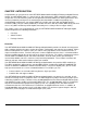
o Dual-color Mode LED to indicate speed, activity, duplex mode, and collision • Easy migration from existing 10 Mbps network to 100 Mbps Fast Ethernet network and Gigabit Ethernet. • Easy upgrade path to add gigabit technology to your network • Flexible installation: o o • Standalone desktop installation 19-inch standard rack-mount Standard 1U case size Package Contents Figure 1-1 shows the package contents of the NETGEAR Model GSM712/GSM712F Managed Gigabit Switch. Figure 1-1.
Figure 1-2. GSM712F Package Contents Verify that your package contains the following: • One GSM712/GSM712F Managed Gigabit Switch • Rubber footpads for tabletop installation • Power cord • One null-modem cable • Rack-mount kit for installing the switch in a 19-inch rack • This user’s guide • One CD ROM • Support Information Card • Warranty & Owner Registration Card If you ordered additional GBIC modules with your switch, they are provided in a separate package.
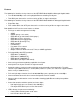
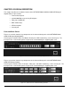
CHAPTER 2: PHYSICAL DESCRIPTION This chapter describes the hardware features of the NETGEAR Model GSM712/GSM712F Managed Gigabit Switch. Topics include: • Front and back panels • 10/100/1000 Mbps auto-sensing RJ-45 ports • Fiber ports (GSM712F) • GBIC module bays • LED descriptions • Console port Front and Black Panels Figures 2-1 and 2-2 show the key components on the front and back panels of the NETGEAR Model GSM712 Managed Gigabit Switch.
10/100/1000 Mbps RJ-45 Ports As Figure 2-1 shows, the GSM712/GSM712F Managed Gigabit Switch has 10 10/100/1000 Mbps RJ-45 ports. These ports are auto-sensing 10/100/1000 Mbps ports: When you insert a cable into an RJ-45 port, the switch automatically ascertains the maximum speed (10 or 100 or 1000 Mbps) and duplex mode (halfor full-duplex) of the attached device. The 10/100/1000 Mbps ports support only unshielded twisted-pair (UTP) cable terminated with an 8-pin RJ-45 plug.
Figure 2-6. Warning! Creating Redundant Paths between Network Devices Gigabit Ethernet Ports (RJ-45 and GBIC Module Bays) Your NETGEAR Model GSM712/GSM712F Managed Gigabit Switch has either 1000BASE-T port or as a GBIC module bay. The default setting for those ports are for the automatic detection of media being used. Which means depend on which connector is used, the port type will be set automatically. Or they can be selected via management interface configuration.
Console Port Your NETGEAR Model GSM712/GSM712F Managed Gigabit Switch has a console port on the front panel. This port is labeled Console and is required for initial configuration of the switch. It also lets you manage the switch using a directly connected VT-100 terminal, personal computer (PC), Apple Macintosh, or UNIX workstation. The terminal, computer, or workstation connects to the console port using the nullmodem cable supplied with your switch.
CHAPTER 3: INSTALLATION This chapter describes the installation procedures for your NETGEAR Model GSM712/GSM712F Managed Gigabit Switch.
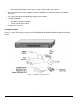
Installing the Switch in a Rack To install the switch in a rack, use the following procedure (and refer to Figure 3-1). To perform this procedure, you need the 19-inch rack-mount kit supplied with your switch. 1. Attach the supplied mounting brackets to the side of the switch. 2. Insert the screws provided in the rack-mount kit through each bracket and into the bracket mounting holes in the switch. 3. Tighten the screws with a #1 Phillips screwdriver to secure each bracket. 4.
Figure 3-2. Installing a Gigabit Ethernet Module Figure 3-3. Installing a Gigabit Ethernet Module Step 4: Checking the Installation Before you apply power: o o o o Inspect the equipment thoroughly. Verify that all cables are installed correctly. Check cable routing to make sure cables are not damaged or are a safety hazard. Be sure all equipment is mounted properly and securely.
8. Connect the female end of the supplied AC power adapter cable to the power receptacle on the back of the switch. 9. Connect the 3-pronged end of the AC power adapter cable to a grounded 3-pronged AC outlet. When you apply power, the Power LED on the switch’s front panel will be Yellow, as it conducts a Power On Self Test (POST). After the switch passes the POST, the Power LED will change to Green and the switch is functional and ready to pass data.
Figure 3-4. System Information 13. The terminal-emulation program should display the System Description page. Hit the ‘ESC’ key to get to the Main Menu page. Figure 3-5.
14. On the Main Menu page, hit the ‘C’ key to select the Set-Up page. Figure 3-6.
15. On the Set Up page, hit the ‘B’ key to select the IP Configuration page. Figure 3-7. IP Configuration 16. On the IP Configuration page, type in the desired IP Address for this switch, followed by the ‘Enter’ key. 17. Now type in the desired Network Mask, followed by the ‘Enter’ key. 18. Now type in the desired Default Gateway, followed by the ‘Enter’ key. 19. Use Ctrl-W to save these new settings. Hit the ‘Y’ key or ‘Enter’ to confirm saving the new settings to NVRAM.
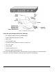
Step 7: Connecting Devices to the Switch The following procedure describes how to connect devices to the switch’s RJ-45 ports. Your NETGEAR Model GSM712/GSM712F Managed Gigabit Switch contains Auto Uplink™ technology, which allows you to attach devices using either straight-through or crossover cables. Figure 3-8. GSM712 Connecting Devices to the Switch Figure 3-9. GSM712F Connecting Devices to the Switch 20.
APPENDIX A: TECHNICAL SPECIFICATIONS This appendix provides technical specifications for the NETGEAR Model GSM712/GSM712F Managed Gigabit Switch. Network Protocol and Standards Compatibility IEEE 802.3 10BASE-T IEEE 802.3u 100BASE-TX IEEE 802.3z 1000BASE-SX IEEE 802.3ab 1000BASE-T IEEE 802.3x flow control Management IEEE 802.1Q Static VLAN (Up to 64) IEEE 802.1p Class of Service (CoS) IEEE 802.1D Spanning Tree Protocol IEEE 802.
Electromagnetic Emissions CE mark, commercial FCC Part 15 Class A VCCI Class A EN 55022 (CISPR 22), Class A C-Tick Electromagnetic Immunity EN 50082-1 EN 55024 Safety CE mark, commercial CSA certified (CSA 22.2 #950) TUV licensed (EN 60 950) UL listed (UL 1950)/CUL IEC950/EN60950 Modules AGM721F GBIC SX module for 1000BASE-SX connections with SC connectors for 50um or 62.
APPENDIX B: TROUBLESHOOTING This chapter provides information about troubleshooting the NETGEAR Model GSM712/GSM712F Managed Gigabit Switch. Topics include: o Troubleshooting chart o Additional troubleshooting suggestions Troubleshooting Chart Table B-1 lists symptoms, causes, and solutions of possible problems. Table B-1. Troubleshooting Chart Symptom Cause Solution Power LED is off. No power is received Link LED is off or intermittent. Port connection is not working.
APPENDIX C: Default Settings This appendix provides the default settings for the NETGEAR Model GSM712/GSM712F Managed Stackable Switch. Feature GSM712/GSM712F Default Setting Port Speed Port Duplex Flow Control (half duplex) Flow Control (full duplex) IP Configuration Password protection User Name Password VLAN IP Multicast Filtering Spanning Tree Protocol Fast Link Traffic Prioritization 802.
M-10130-02 May 2003