Managed Switch Hardware Ins tallat i o n G ui d e Models: M4100 Series August 2016 202-11217-04 350 East Plumeria Drive San Jose, CA 95134 USA
NETGEAR Managed Switch Support Thank you for purchasing this NETGEAR product. You can visit www.netgear.com/support to register your product, get help, access the latest downloads and user manuals, and join our community. We recommend that you use only official NETGEAR support resources. Contact your Internet service provider for technical support. Conformity For the current EU Declaration of Conformity, visit http://kb.netgear.com/app/answers/detail/a_id/11621.
Contents Chapter 1 Introduction Front Panels and LEDs. . . . . . . . . . . . . . . . . . . . . . . . . . . . . . . . . . . . . . . . . . . . . . . . . 4 Rear Panels . . . . . . . . . . . . . . . . . . . . . . . . . . . . . . . . . . . . . . . . . . . . . . . . . . . . . . . . . . 9 Safety Instructions . . . . . . . . . . . . . . . . . . . . . . . . . . . . . . . . . . . . . . . . . . . . . . . . . . 10 Chapter 2 Hardware Installation Package Contents . . . . . . . . . . . . . . . . . . . . . . . . . .
1. 1 Introduction The NETGEAR ProSAFE® M4100 Series managed switches provide state-of-the-art, high-performance, IEEE-compliant network solutions. They include powerful management features that you can use to eliminate bottlenecks, boost performance, and increase productivity.
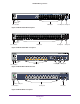
NETGEAR Managed Switch LEDs USB port Reset button SFP ports RJ-45 ports Figure 1. M4100-26G front panel Power Fan Reset Combo Ports RPS USB RJ45 SPD/Link/ACT mode: Green = 1G Yellow = 10/100M Blink = ACT SFP SPD/Link/ACT mode: Green = Link at 1G Yellow = Link at 100M Blink = ACT LEDs USB port Reset button SFP ports RJ-45 ports Figure 2. M4100-50G front panel LEDs USB port Reset button POE ports RJ-45 ports SFP ports Figure 3.
NETGEAR Managed Switch LEDs USB port Reset button POE ports RJ-45 ports SFP ports Figure 5. M4100-26G-POE front panel LEDs USB port Reset button POE ports RJ45 ports SFP ports Figure 6. M4100-50G-POE+ front panel LEDs USB port Reset button RJ45 ports POE ports SFP ports Figure 7. M4100-D10-POE Front Panel LEDs USB port Reset button RJ45 ports Figure 8.
NETGEAR Managed Switch M4100-24G-POE+ PoE SPD/Link/ACT PoE (Max 30W per port): Off = No PD Green = PoE Powered Yellow = PoE Fault Power Fan SFP SPD/Link/ACT mode Green = Link at 1G Yellow = Link at 100M Blink = ACT RJ45 SPD/Link/ACT mode: Green = 1G Yellow = 10/100M Blink = ACT PD MaxPoE USB Reset USB LEDs USB port Reset button POE ports SFP ports DB9 Console(USB) 115200,N,8,1 SPD/Link/ACT Console Mini switch USB port Figure 9.
NETGEAR Managed Switch Table 1. LED descriptions LED Description Power Solid green: Internal power supply operating normally and supplying power to the switch. Solid yellow: The system is in boot-up stage. Blinking yellow: Power module is present but has failed. Off: Power is disconnected. Fan Solid green: The fan is operating normally. Solid yellow: The fan has failed. Off: No fan is detected. RPS Solid green: RPS connected (using internal power supply’s power).
NETGEAR Managed Switch Table 1. LED descriptions (continued) LED Description Link/ACT (RJ45 port) Off: No link is established on the port. Solid green: A valid link is established on the port. Blinking green: Packets transmission or reception is occurring on the port. Note: If a combo port media changes to fiber, the copper port LED changes to off status. SPD (RJ45 port) Off: No link is established on the port. Solid green: A valid 1000 Mbps link is established on the port.
NETGEAR Managed Switch Console switch Lock Console ports Power adapter connector Figure 14. M4100-D10-POE and M4100-D12G rear panels Console port RPS power supply connector Lock AC power connector Figure 15. M4100-12GF, 24G-POE+, 12G-POE+ rear panel Lock Console port AC power connector Figure 16. M4100-D12G-POE+ rear panel Safety Instructions Use the following safety guidelines to ensure your own personal safety and to help protect your system from potential damage.
NETGEAR Managed Switch - • Opening or removing covers that are marked with the triangular symbol with a lightning bolt might expose you to electrical shock. Only a trained service technician should service components inside these compartments. If any of the following conditions occur, unplug the product from the electrical outlet and replace the part or contact your trained service provider: - The power cable, extension cable, or plug is damaged. - An object has fallen into the product.
NETGEAR Managed Switch • Observe extension cable and power strip ratings. Make sure that the total ampere rating of all products plugged into the extension cable or power strip does not exceed 80 percent of the ampere ratings limit for the extension cable or power strip. • To help protect your system from sudden, transient increases and decreases in electrical power, use a surge suppressor, line conditioner, or uninterruptible power supply (UPS).
2. Hardware Installation 2 This chapter explains how to install the hardware for the managed switches. Package Contents Each switch is packed and shipped separately.
NETGEAR Managed Switch You can also take the following steps to prevent damage from electrostatic discharge (ESD): 1. When unpacking a static-sensitive component from its shipping carton, leave it in the antistatic package until you are ready to install it. Just before unwrapping the antistatic package, discharge static electricity from your body. 2. Before moving a sensitive component, place it in an antistatic container or package. 3. Handle all sensitive components in a static-safe area.
NETGEAR Managed Switch For more information, see Connect to Power and Check the LEDs on page 20. Select a Location The switch can be mounted in a standard 19-inch (48.26-centimeter) rack, wall mounted, or left freestanding (placed on a tabletop). The site where you install the switch might greatly affect its performance. Before installing the switch or switches, make sure that the chosen installation location meets the following site requirements. Table 2.
NETGEAR Managed Switch Install the Switch You can install the switch on a flat surface or in a standard 19-inch rack. Install the Switch on a Flat Surface The switch ships with four self-adhesive rubber footpads. Stick one rubber footpad on each of the four concave spaces on the bottom of the switch. The rubber footpads cushion the switch against shock and vibrations. Install the Switch in a Rack Note: The M4100-D10-PoE is not rack mountable.
NETGEAR Managed Switch 2. Use the provided Phillips head screws to fasten the brackets to the sides of the switch. Mounting bracket E+ G-PO 0-24 M410 3. Tighten the screws with a No. 1 Phillips screwdriver to secure each bracket. 4. Align the bracket and rack holes. Use two pan-head screws with nylon washers to fasten each bracket to the rack. 5. Tighten the screws with a No. 2 Phillips screwdriver to secure the switch in the rack.
NETGEAR Managed Switch Install the Switch on a Wall (M4100-D10-PoE Only) If you install the switch on a wall in the vertical position, be sure to orient the switch as shown in the following figure. The switch should be mounted so that the ports face up or down. Do not mount the switch with the ports to the side. The exhaust air should come out the side of the switch case. Note: The switch should have a minimum of 5 inches (130 millimeters) of clearance on all sides. 1.
NETGEAR Managed Switch Install the M4100-D12G or M4100-D10-PoE Using Magnets If you use the magnets (included) to install the M4100-D12G or M4100-D10-PoE switch to a vertical metal surface, the maximum height above the floor is 75 centimeters (29.5 inches). Be sure to orient the switch as shown in the following figure. Exhaust air should come out the side of the switch case. 1. Attach the magnets to the switch using a No. 1 Phillips screwdriver and 4 screws (provided). See the following figure. 2.
NETGEAR Managed Switch Check the Installation Before you apply power, perform the following checks: 1. Inspect the equipment thoroughly. 2. Verify that all cables are installed correctly. 3. Check cable routing to ensure that cables are not damaged and will not create a safety hazard. 4. Be sure that all equipment is mounted properly and securely. Connect to Power and Check the LEDs The switch does not have an on/off switch. The only way to apply or remove power is to connect or disconnect the power cord.
NETGEAR Managed Switch Note: If the PD LED on the front panel of the M4100-D12G and M4100-D12G-POE+ blinks green, port 1 is connected to a IEEE802.3af PoE device. Check the PoE device specification to make sure that it supports IEEE802.3at. If the Power LED does not light up, check that the power cable is plugged in correctly and that the power source is good. For more information, see Troubleshooting on page 24. SFP Modules SFP modules (sold separately) can be inserted directly into the switch’s ports.
NETGEAR Managed Switch Connect Equipment to the Switch You can connect devices, a Gigabit Ethernet module, and/or a console to the switch. RJ-45 Ports The switch uses Auto Uplink technology, which enables you to attach devices using either straight-through or crossover cables. Use a Category 5 (Cat 5) unshielded twisted-pair (UTP) cable terminated with an RJ-45 connector. Note: Ethernet specifications limit the cable length between the switch and the attached device to 328 feet (100 meters).
NETGEAR Managed Switch 3. Connect the other end of the cable to a workstation or terminal. 4. If you attached a workstation, start a terminal emulation program. • Microsoft Windows users can use HyperTerminal if it comes with the Windows operating system. If it does not, you need to install another third-party terminal emulator such as Tera Term. • Macintosh users can use ZTerm. • UNIX users can use a terminal-emulator such as TIP. 5.
3. 3 Troubleshooting Troubleshooting Chart The following table lists symptoms, causes, and solutions to possible problems. Table 3. Troubleshooting chart Problem Cause Solution Power LED is off. No power is received. Check the power cord connections for the switch at the switch and the connected device. Make sure that all cables used are correct and comply with Ethernet specifications. Link LED is off or intermittent. Port connection is not working.
NETGEAR Managed Switch Additional Troubleshooting Suggestions If the suggestions in Table 3 do not resolve your problem, refer to the troubleshooting suggestions in this section. • Network adapter cards: Make sure that the network adapter cards installed in the computers are in working condition and the software driver has been installed. • Configuration: If problems occur after you change the network configuration, restore the original connections.
A. A Technical Specifications Table 4.
NETGEAR Managed Switch Table 4. M4100-26G, 50G, 26G-POE, 50G-POE+, and D12G Gigabit switch physical specifications Specification M4100-26G M4100-50G M4100-26G-PO (GSM7224v2h2) (GSM7248v2h2) E (GSM7226LP) Acoustic noise (dB) (ANSI-S10.12) 35.6dB @ 25°C 37.2 dB @ 25°C 36.6 dB @ 25°C 47.7 dB @ 25°C 0 Maximum power consumption (W) (100–240V AC, 50–60 Hz) 31.6 49.5 272.90 M4100-50G-PO E+ (GSM7248P) 555.5 M4100-D12G (GSM5212) 18.80 Table 5.
NETGEAR Managed Switch Specification M4100-24G-POE+ (GSM7224P) M4100-D12G-POE + (GSM5212P) M4100-12G-POE+ (GSM7212P) M4100-12GF (GSM7212F) Acoustic noise (dB) (ANSI-S10.12) 49.9 35.1 dB @ 25dC with AC mode 0dB with PD mode 50.3 48 Maximum power consumption (W) (100–240V AC, 50–60 Hz) 553.00 167.00 452.00 161.00 Table 6.
NETGEAR Managed Switch Table 7. Technical specifications Feature Description IEEE Network Protocol and Standards compatibility • • • • • • • • 802.3i 10BASE-T 802.3u 100BASE-TX 802.3z 1000BASE-X 802.3ab 1000BASE-T 802.3az EEE 802.3x flow control 802.3af power over Ethernet 802.
NETGEAR Managed Switch Table 7. Technical specifications (continued) Feature Description QoS • DiffServ QoS System Service • • DHCP, BOOTP Relay DHCP server Security • • • • • • • • • • • • • Radius TACACS+ 802.1x MAC filter Port security Protected port Private group Storm control DHCP snooping IP source guard Dynamic ARP inspection MAC ACL (inbound) IP ACL (inbound) Address database size 16 K MAC addresses per system 10/100/1000 buffer memory Max support 1.
NETGEAR Managed Switch Table 7. Technical specifications (continued) Feature Description Safety CE mark, UL listed (UL 1950)/cUL, CB, CCC Security • • • • • • • • • • • • • Radius TACACS+ 802.
B. Default Configuration Settings Table 8.
NETGEAR Managed Switch Table 8. M4100 Series switch default settings (continued) Feature Default Setting GMRP Disabled IP routing Disabled MAC address aging 300 seconds SNMP community public (read-only access), private (read/write access) DHCP Server Disabled VLAN Ingress filtering Enabled IP multicast filtering Disabled 802.