
Installation Manual

Hardware Installation
20
NETGEAR Managed Switch
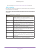
Check the Installation
Before you apply power, perform the following checks:
1. Inspect the equipment thoroughly.
2. Verify that all cables are installed correctly.
3. Check cable routing to ensure that cables are not damaged and will not create a safety
hazard.
4. Be sure that all equipment is mounted properly and securely.
Connect to Power and Check the LEDs
The switch does not have an on/off switch. The only way to apply or remove power is to
connect or disconnect the power cord. Before you connect the power cord, select an AC
outlet that is not controlled by a wall switch (which can turn off power to the switch).
To apply AC power:
1. Select an appropriate outlet.
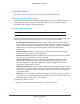
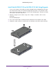
2. Connect one end of the AC power adapter cable (M4100-DG12 or M4100-D10-PoE) or the
AC power cord to the rear of the switch, and the other end to a grounded three-pronged AC
outlet.
Note: The M4100-26G, 50G, 26-PoE, 26G-PoE, 50-PoE+, 50G-PoE, 12GF,
24G-POE+, 12G-POE+ can also obtain power from an RPS.
Supported RPS models are the RPS5412 and RPS4000.
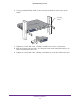
Note: Normally the M4100-D12G and M4100-D12G-POE+ will get power
using the supplied power adapter. These switches can also get power
from a PSE (power sourcing equipment) switch if AC power is not
available. Connect port 1 of these switches to a PSE switch. The PSE
device should support IEEE802.3at so that it can provide full power to
these switches for system operation. If the PSE device used does not
support IEEE802.3at, theses switches might not operate correctly.
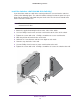
3. Check the Power LED on the front panel of the switch.
The LED should light in the following sequence:
• The LED turns yellow as the switch runs a power-on self-test (POST).
• If the switch passes the test, the LED turns green. The switch is working and ready to
pass data.
• If the POST fails, the Power LED blinks yellow.