M-10114-01
© 2003 by NETGEAR, Inc. All rights reserved. Trademarks © 2003 NETGEAR, Inc. NETGEAR ® , the Netgear Logo, the Gear Guy, and Everybody’s connecting are trademarks or registered trademark of Netgear, Inc. in the United States and/or other countries. Microsoft, Windows, and the Windows logo are trademarks, or registered trademarks of Microsoft Corporation in the United States and/or other countries. Other brand and Product names are trademarks or registered trademarks of their respective holders.
Warning: This is a Class A product. In a domestic environment, this product may cause radio interference, in which case the user may be required to take appropriate measures. Canadian Department of Communications Radio Interference Regulations This digital apparatus (NETGEAR Model GSM7324 Managed Gigabit Switch) do not exceed the Class A limits for radio-noise emissions from digital apparatus as set out in the Radio Interference Regulations of the Canadian Department of Communications.
CONTENTS CHAPTER 1: INTRODUCTION...................................................................................................................... 5 Overview .....................................................................................................................................................................5 Features ......................................................................................................................................................................
Figures FIGURE 1-1. PACKAGE CONTENTS.................................................................................................................................................7 FIGURE 2-1. FRONT PANEL OF THE GSM7324 MANAGED LAYER 3 GIGABIT ETHERNET SWITCH .........................................9 FIGURE 2-2. BACK PANEL OF THE GSM7324 MANAGED LAYER 3 GIGABIT ETHERNET SWITCH ...........................................9 FIGURE 2-3. WARNING! CREATING REDUNDANT PATHS BETWEEN NETWORK DEVICES ..............
CHAPTER 1: INTRODUCTION Congratulations on your purchase of a NETGEAR Model GSM7324 Managed Layer 3 Gigabit Ethernet Switch! Your NETGEAR Switch is a state-of-the-art, high-performance, IEEE-compliant network solution designed for users who want ease of use along with powerful management features you can use to eliminate bottlenecks, boost performance, and increase productivity. This Installation Guide will assist you in getting your switch up and running.
Features The following list identifies the key features of the NETGEAR Model GSM7324 Managed Layer 3 Gigabit Ethernet Switch.
o • SNMP-based Network Management Software (NMS) Automatic hardware configuration on all Ethernet RJ-45 ports o o o Auto-sensing and auto-negotiating speed Auto Uplink™ on all ports to automatically make the right connection (MDI/MDI-X) Full- and half-duplex functions • Automatic address learning function to build the packet-forwarding information table. The table contains up to 8,000 media access control (MAC) addresses (that is, the switch can support networks with as many as 8,000 devices).
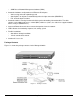
Verify that your package contains the following: GSM7324 Managed Layer 3 Gigabit Ethernet Switch Rubber footpads for tabletop installation Rubber caps for the 4 SFP sockets Power cord Null-modem console cable Rack-mount kit for installing the switch in a 19-inch rack This Installation Guide CD ROM Support Information Card Warranty If you ordered additional SFP modules with your switch, they are provided in a separate package. If any item is missing or damaged, contact your place of purchase immediately.
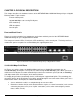
CHAPTER 2: PHYSICAL DESCRIPTION This chapter describes the hardware features of the NETGEAR Model GSM7324 Managed Layer 3 Gigabit Ethernet Switch.
• After ascertaining this information, the switch automatically configures the RJ-45 port to enable communications with the attached device, without requiring user intervention. In this way, the Auto Uplink technology eliminates the need for setting uplink connections or being concerned about whether to use crossover or straight-through cables when attaching devices. Figure 2-3.
LED Descriptions The front panel of the NETGEAR Model GSM7324 Managed Layer 3 Gigabit Ethernet Switch has LEDs that provide a quick and accurate display of port speed, activity, and link state. The Gigabit Ethernet SFP ports also have LEDs that show link and activity status. Table 2-1 summarizes the LEDs on the switch and Gigabit Ethernet module. Table 2-1.
For more information about console-port connections, see “Connecting to the Console Port” in Chapter 3 Installation. For more information about managing the switch, see the User Manual located on the CDROM.
CHAPTER 3: INSTALLATION This chapter describes the installation procedures for your NETGEAR Model GSM7324 Managed Layer 3 Gigabit Ethernet Switch.
Step 2: Installing the Switch You can install your NETGEAR Model GSM7324 Managed Layer 3 Gigabit Ethernet Switch on a flat surface or in a standard 19-inch rack. Installing the Switch on a Flat Surface The switch ships with four self-adhesive rubber footpads. Stick one rubber footpad on each of the four concave spaces on the bottom of the switch. The rubber footpads cushion the switch against shock/vibrations.
1. Connect the female end of the supplied AC power adapter cable to the power receptacle on the back of the switch. 2. Connect the 3-pronged end of the AC power adapter cable to a grounded 3-pronged AC outlet. When you apply power, the Power LED on the switch’s front panel will be Yellow, as it conducts a Power On Self Test (POST). After the switch passes the POST, the Power LED will change to Green and the switch is functional and ready to pass data. If the POST failed, the Diagnostic LED will turn on.
To install additional Gigabit Ethernet module, repeat this procedure Figure 3-3. Installing a Gigabit Ethernet fiber Module into an GSM7324 Step 7: Connecting to the Console Port to Manage the Switch (initial configuration) To learn the IP address, you must first access the Command Line management via the console interface.
Figure 3-4. System Information. 5. The login name is “admin”. And there is no password assigned. We strongly recommend you enable password for admin access to secure access to the switch management function. After successful login, the screen should show (GSM7324)> prompt. Enter “show sysinfo”, and it will display the management CPU’s IP address.
Sysinfo page. To use your web browser, simply type the IP address in the URL address bar and hit enter. If you want to use an SNMP management application, you will need to note the IP address and to configure the SNMP settings in your switch so that it will respond to SNMP requests. This configuration can be done through either the console or web browser GUI. See User Guide on how to enable SNMP access. Note: The switch IP address is by default using DHCP mode to assign its address.
APPENDIX A: TECHNICAL SPECIFICATIONS This appendix provides technical specifications for the NETGEAR Model GSM7324 Managed Layer 3 Gigabit Ethernet Switch. Network Protocol and Standards Compatibility IEEE 802.3 10BASE-T IEEE 802.3u 100BASE-TX IEEE 802.3z 1000BASE-SX IEEE 802.3ab 1000BASE-T IEEE 802.3x flow control Layer 2 Services IEEE 802.1Q Static VLAN (Up to 4k) IEEE 802.1p Class of Service (CoS) IEEE 802.1D Spanning Tree Protocol (STP) IEEE 802.1w Rapid Spanning Tree Protocol (RSTP) IEEE 802.
Interface 24 RJ-45 connectors for 10BASE-T, 100BASE-TX, and 1000BASE-T (Auto Uplink™ on all ports) 4 Gigabit Interface Converter (SFP) slots for SFP modules RS-232 Console Port LEDs Per port (10/100/1000 for TP and Gigabit for fiber): Link, Speed, and Activity. Per device: Power, fan, and status.
Safety CE mark, commercial CSA certified (CSA 22.
APPENDIX B: TROUBLESHOOTING This chapter provides information about troubleshooting the NETGEAR Model GSM7324 Managed Layer 3 Gigabit Ethernet Switch. Topics include: Troubleshooting chart Additional troubleshooting suggestions Troubleshooting Chart Table B-1 lists symptoms, causes, and solutions of possible problems. Table B-1. Troubleshooting Chart Symptom Cause Solution Power LED is off. No power is received Link LED is off or intermittent. Port connection is not working.
Configuration If problems occur after altering the network configuration, restore the original connections and determine the problem by implementing the new changes, one step at a time. Make sure that cable distances, repeater limits, and other physical aspects of the installation do not exceed the Ethernet limitations. Switch Integrity If required, verify the integrity of the switch by resetting the switch.
APPENDIX C: Default Settings This appendix provides the default settings for the NETGEAR Model GSM7324 Managed Layer 3 Gigabit Ethernet Switch.
M-10114-01