802.11b Wireless PC Card 2.
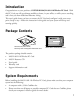
Introduction Congratulations on your purchase of NETGEAR MA521 802.11b Wireless PC Card. With this PC Card you will get ultimate mobility at home, in your office, or while you are traveling, and it frees you from traditional Ethernet wiring. This user’s guide shows you how to connect the PC Card and configure it with your access point. Setup is easy – follow the instruction in this guide and your system will be up and running quickly. Package Contents Wireless PC Card 32-bit CardBus MA521 802.11b • 2.
• Windows 98/Me/2000/XP (be sure to have the Windows Installation CD-ROM ready for use during installation). • At least 5 Mbytes disk space for installing the driver and utility programs. LED Indicators There are two LEDs on the MA521 802.11b Wireless PC Card: Pwr and Lnk. The green Pwr LED indicates the power of the card. The green Lnk LED indicates the wireless link condition of the station with another wireless node or the associated Access Point.
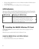
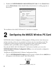
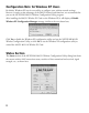
3. The Autostart Wizard screen will appear, as shown here: 4. Click the Install Driver & Utility option. 5. If the Autorun wizard does not automatically start, go to your Windows Start menu and choose Run, and type D:/Setup.exe (“D” represents your CD-ROM drive letter), and click OK. 6. The InstallShield Wizard screen will appear. Click Next to continue. 7. The Choose Destination Location screen will display the default Destination Folder.
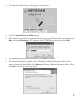
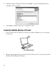
8. Modify the Program Folders field, if desired. Click Next to continue. Install Shield will start copying files onto your system. 9. Click Finish to complete installing the Configuration Utility. Install the MA521 Wireless PC Card 1. Insert the MA521 802.11b Wireless PC Card into an available CardBus slot on your computer as shown here. 80 2.1 1b -b ar us ss dB ele C ir it W 2 H z 3 •2 .4 G M A PC 2 a 1 C 5 rd MA521 Wireless PC Card in a Notebook Computer 2.
3. 4. Follow the on-screen instructions to install the driver for the MA521 802.11b Wireless PC Card. • For Windows 98/Me users, once the [Please insert the disk labeled “Windows 98/Me CD-ROM,” and then click OK] window appears, enter the path corresponding to the appropriate drives and click OK. Usually these files can be found at C:\Windows or C:\Windows\System. • For Windows 2000 users, a Digital Signature Not Found message may appear. Click Yes to proceed.
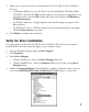
5. Double-click NETGEAR MA521 802.11b Wireless PC Card. On the General folder tab, the Device Status window should indicate that the device is working properly, as shown here: The installation of the MA521 Wireless PC Card driver is complete. 2 Configuring the MA521 Wireless PC Card NETGEAR’s wireless Configuration Utility program will help you learn more about your wireless network, so that you can customize it to better suit your networking needs.
About the MA521 SysTray Application The SysTray (System Tray) resides on one end of the taskbar in the Microsoft Windows Desktop. It displays interface icons for memory-resident applications that execute continuously in the background, such as the clock, speaker volume, and virus detection.
Configuration Note for Windows XP Users By default, Windows XP uses its own utility to configure your wireless network settings, however, in order to take advantage of the MA521 features and functions, we recommend that you use the NETGEAR MA521 Wireless Configuration Utility program.
This table describes the information shown in the Status section of the dialog box: Status Description Connected to Indicates the SSID and MAC address of the associated Access Point when the MA521 802.11b Wireless PC Card is configured in Infrastructure mode. Network mode Indicates the network mode of the MA521 802.11b Wireless PC Card (Infrastructure or 802.11 Ad-Hoc). Channel Indicates the wireless channel currently in use.
This table describes the options available from the Configuration section: Configuration Description Network mode Configurable between 802.11 Ad-hoc and Infrastructure modes. In 802.11 Ad-hoc mode, the wireless nodes form their own local network where the end nodes communicate peer-to-peer without an Access Point. In Infrastructure mode, the wireless searches all available wireless channels to associate with an Access Point.
To activate the WEP Encryption, make sure the Enable Encryption box displays a checkmark (as shown on previous page). WEP Encryption options will be displayed, as shown on the previous page. You may make changes, as detailed here: 1. Select one of the two options: Create with Passphrase or Manual Entry. A Passphrase makes you easier to enable WEP because it automatically generates the WEP hexadecimal numbers for the key. If the wireless network Access Point uses a Passphrase, you can also use that here.
This table describes the options available from the Security section: Security Description Enable Encryption Enables the data encryption for the wireless node. If you disable the data encryption (by unchecking the box) then no encryption method will be used; this is also called Open System data encryption. To enable encryption is to use the Shared Key data encryption method. Create with Passphrase A Passphrase is use to automatically generate the WEP hexadecimal numbers for the key.
This table describes the options available from the Security section: Status Description Transmit Rate The Transmit Rate field allows to define the data transfer rate. The default value if Fully Automatic. In this case, the best transfer rate is negotiated between this wireless node and access point or another wireless note that it is communicating with. Other option values for this field are 1, 2, 5.5 and 11 Mbps. Power Saving Power saving options are Off, Normal, and Maximum.
Profile Section The Profile area allows you to set values for all parameters by selecting a previously defined profile. To create a profile, in the Profile Name field, type a Profile Name; for example: Home, Office. When you are done, click the Save button in the Profile area, and click Apply. If one of the profiles is no longer used, display the name in the Profile Name field, then choose Delete. You can add and modify multiple profiles at any time.
To display Access Points around the working environment, select the Re-Scan button. In addition to showing the MAC Address of each Access Point, you can also view the Channel, Signal, Security, and Network Modes. Click OK to continue, or select another tab. Statistics Section The Statistics section of the Configuration Utility dialog box indicates the real-time Transmit and Receive packets performance in graph form and also displays the performance statistics in figures.
About Section The About section of the Configuration Utility dialog box shows the regulatory domain: FCC for US, ETSI for Europe, MKK for Japan; the MAC address and the release information of both the device driver for the Wireless Adapter and the Wireless Configuration Utility software. Click OK to continue, or select another tab.
80 2.1 1b -b s Bu es rd el Ca ir it W H z 32 •2 .4 G Ad-Hoc s M a 21 C A5 PC rd 80 2.1 1b MA521 Wireless PC Card in a Notebook Computer -b s Bu es rd el Ca ir it W H z 32 •2 .4 G s M a 21 C A5 PC rd MA521 Wireless PC Card in a Notebook Computer 80 2.1 1b -b s Bu es rd el Ca ir it W H z 32 •2 .
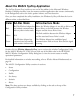
Notebook PC with MA111 802.11b Wireless USB Adapter Macintosh with Ethernet connection Desktop PC with MA111 802.11b Wireless USB Adapter R G E A N E T Internet 3 MR814 802.11b Cable/DSL Wireless 4-port Router Desktop PC with FA311 Ethernet Card Cable/DSL Modem Desktop PC with MA321 802.11b Wireless PCI Adapter Notebook PC with MA521 802.11b Wireless PC Card Notebook PC with MA521 802.
Authentication and WEP Encryption The absence of a physical connection between nodes makes the wireless links vulnerable to information theft. To provide a certain level of security, IEEE 802.11 standard has defined two types of authentication methods, Open System and Shared Key. Open System authentication is a null algorithm. Shared Key authentication is an algorithm where both the transmitting node and the receiving node share an authentication key to perform a checksum on the original message.
Wireless Channel Selection 802.11b IEEE 802.11b wireless nodes communicate with each other using radio frequency signals in the ISM (Industrial, Scientific, and Medical) band between 2.4 GHz and 2.5 GHz. Neighboring channels are 5 MHz apart. However, due to spread spectrum effect of the signals, a node sending signals using a particular channel will utilize frequency spectrum 12.5 MHz above and below the center channel frequency.
Troubleshooting Problem Cause Solution • Remove and reinsert the MA521 Wireless No lights are lit The MA521 Wireless PC PC Card. on the Wireless Card is not inserted PC Card properly into the CardBus • Check the device manager in Windows to see slot on your PC. Or the if the adapter card is properly recognized in proper MA521 Wireless PC the Windows operating system. Reload the Card driver is not loaded. driver if necessary.
Statement of Conditions In the interest of improving internal design, operational function, and/or reliability, NETGEAR reserves the right to make changes to the products described in this document without notice.NETGEAR does not assume any liability that may occur due to the use or application of the product(s) or circuit layout(s) described herein.
Canadian Department of Communications Radio Interference Regulations This digital apparatus (Model MA521 Wireless PC Card) does not exceed the Class B limits for radio-noise emissions from digital apparatus as set out in the Radio Interference Regulations of the Canadian Department of Communications.
Technical Support PLEASE REFER TO THE SUPPORT INFORMATION CARD THAT SHIPPED WITH YOUR PRODUCT. By registering your product at www.NETGEAR.com/register, we can provide you with faster expert technical support and timely notices of product and software upgrades. NETGEAR, INC. Support Information Phone: 1-888-NETGEAR (For US & Canada only) - 24x7 phone support See Support Information card for other countries. E-mail: support@NETGEAR.com (24x7 online support) www.NETGEAR.com ©2003 NETGEAR, Inc.