Page 1 of 36 MP115 A/V Digital Media Player User’s Guide 2BDF0-020017 REV.
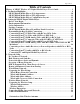
Page 2 of 36 Table of Contents History of MP115 Wireless A/V Digital Media Player User’s Guide ............................. 1 1. Production Highlights ..................................................................................................... 4 MP115 Digital Media Player (NA) Appearance........................................................ 10 MP115 Digital Media Player (UK) Appearance ....................................................... 11 MP115 Digital Media Player Configuration Layout ...
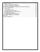
Page 3 of 36 Fine Tuning the Digital Media Player Antenna (Wireless) .................................... 27 Remote Control ............................................................................................................ 27 Remote Control Buttons Function............................................................................ 27 Remote Control Battery Installation ........................................................................ 29 4.
Page 4 of 36 MP115 Wireless Audio/Video Digital Media Player User’s Guide Product Highlights This document describes in detail the specification of a Wireless Audio/Video Digital Media Player for the MP115 designed to support UPnP compatible, and UPnP A/V conformant, networked audio/video capable of playing streaming audio (formats are supported: MP3, WMA, MAV, and AAC), video (formats are supported : MPEG1/2/4 and Divx4/5), and images (formats are supported: GIF, JPG, BMP, and TIFF) via a wired or wireles
Page 5 of 36 MP115 Digital Media Player (NA) Appearance 2BDF0-020017 REV.
Page 6 of 36 MP115 Digital Media Player (UK) Appearance 2BDF0-020017 REV.
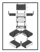
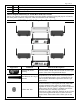
Page 7 of 36 MP115 Digital Media Player Configuration Layout Streaming Media Server is a client-server system that comprised of a client and a server device. The MP115 Digital Media Player has no permanent storage thus it is called the “client” because its purpose is to browse and playback content. The PC has permanent storage and thus it is called the “server”. Images, movies, and music files can all be served to the Digital Media Player from the PC.
Page 8 of 36 Setting the MP115 Digital Media Player Before Your Begin • Refer to the manual of your TV, stereo receiver, or other equipment as necessary. Note the style of jacks and connectors on the other equipment. Determine how to choose different audio and video in channel on your other equipment so you can see and hear the images, movies, and music on the TV, stereo, etc. • Disconnect all equipment from the power outlets.
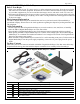
Page 9 of 36 Resource CD Installation Guide Warranty/Support Information Card User’s Manual MP115 Digital Media Player Front/Rear Panel Overviews Before you continue, please take a moment to become familiar with the locating and purpose of controls, the status panel, connectors, and ports, which are illustrated in the following: MP115 Digital Media Player Front/Rear Panel Overviews Appearance 2BDF0-020017 REV.
Page 10 of 36 YPbPr Video Out Jacks Analog Audio/RCB Video Out Jacks SCART Video Out Jack USB Port Jack Ethernet Port Jack Reset Switch Power AC Inlet Jack YPbPr is a scaled version of the YUV (YUV is the color space used by the NTSC and PAL video system.) color space, with specific levels and timing signals, designed to interface equipment together. For HDTV interfaces, 0.3V tri-level sync signals are used, while for SDTV interface, a 0.3V bi-level sync signal is present.
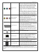
Page 11 of 36 Classification OOOO OOO OO OO OO OOO OO Description Video Connection Section YPbPr video provides the best picture quality. Details are on page 16. S-video provides excellent picture quality. Details are on page 16. RGB Analog video provides good picture quality. Details are on page 17. This is a 21-pin connector supported by many consumer video components in Europe. It allows mono or stereo audio and composite, S-video, or RGB video to be transmitted between equipment.
Page 12 of 36 Connecting Your TV RGB Analog Video with RCA to RCA Jack • If your TV has a RGB video input, you can use the supplied video cable with RCA line input jack ( which has yellow marking). Refer to the connection diagram given below, then connect the video cable to the Digital Media Player’s VIDEO jack. Connect the other end of the video cable to the corresponding VEDIO jack on the TV. Note: On the TV, the VIDEO IN jack is usually yellow and might be labeled VIDEO, CVBS, COMPOSITE, or BASEBAND.
Page 13 of 36 Connecting Your TV Audio/Video with RCA to SCART Jacks • If you have a (SCART to RCA) A/V cable (not included) that one end of the A/V cable with RCA line input jacks which has yellow, white, and red markings), and another end of the A/V cable with SCART line input jack. Refer to the connection diagram given below, then connect the SCART line input jack of the A/V cable to the Digital Media Player’s SCART video jack.
Page 14 of 36 IN jack on your RF modulator. • Connect an RF coaxial cable (not supplied) to the RF OUT, ANTENNA OUT, or to TV jack on the RF modulator. The RF OUT jack may be labeled differently among different brands. Refer to the instructions provided with your RF modulator. Connect the other ends of the same RF coaxial cable to the ANTENNA IN or RF-IN jack on your TV. Note: Your RF modulator should have a Channel 3/4 switch.
Page 15 of 36 Connect the other ends of the audio cable to the AUDIO L/R audio jacks on the TV. Match the cable colors to the jack colors. Connecting TV and Digital Media Player Power • Plug the power cord (female) into the power inlet jack on the Digital Media Player. Plug the other end ( male) of the power cord into an active power outlet. Also plug the power cord of the TV into an active power outlet.
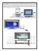
Page 16 of 36 Network Setup Many books have been written about the subject of networking. Therefore, this section is only intended to provide a brief overview of how Digital Media Player works in a home network environment and covers only those issues essential to setting up a proper network for using Digital Media Player. Do You have a Network If you have a single PC and you connect to the Internet with a phone line, chances are you do not have a network.
Page 17 of 36 Router and Internet Connection Sharing A “router” is a network device that forwards or “router” TCP/IP data between your network and the Interne. Routers are typically separate boxes that connect to your network and the Internet. However, Windows 98 S/E (and higher) provides a feature called “Internet Connection Sharing” (“ICS”) which lets a PC connected to the Internet act as a simple router and DHCP server.
Page 18 of 36 all cases, the router works as a DHCP server (i.e., it assigns network address). Set the Digital Media Player network settings to wired using DHCP addressing. From the main home screen: >Press Options >Select Network Setup >Set Connection to Wired (Ethernet) >Select Address >Set Configuration to DHCP >Press left arrow to return to Media Adapter options >Select Apply Changes to apply the network changes Once the Digital Media Player restarts you will be returned to the main home screen.
Page 19 of 36 Choose a static address for your PC and one for your Digital Media Player. Use a netmask of 255.255.255.0 for both. To configure the Digital Media Player for a crossover cable: >Press Options >Select Network Setup >Set Connection to Wired (Ethernet) >Select Address >Set Configuration to Static >Set IP Address to 192.168.0.2 >Set Netmask to 255.255.255.
Page 20 of 36 Wireless Infrastructure Most wireless networks communicate in Infrastructure mode. To configure the Digital Media Player network settings for wireless Infrastructure and DHCP dynamic addressing: >Press Options >Select Network Setup >Set Connection to Wireless (Infrastructure) >The Digital Media Player will scan for wireless local area networks (WLAN). Select WLAN to choose your wireless network if it is not already chosen.
Page 21 of 36 To configure the Digital Media Player network settings for wireless Ad Hoc mode and static addressing: >Press Options >Select Network Setup >Set Connection to Wireless (Ad Hoc) >Select Address >Set Configuration to static >Set the IP Address to 192.168.0.2 >Select Netmask to 255.255.255.
Page 22 of 36 peripheral. Avoid places that expose the components to dust, grease, extreme temperatures, or high humidity. An environment you’d consider suitable for a stereo receiver and network should also serve your PC well. Arrange the components securely on a firm, level surface. Orientation of the Wireless Antennas Proper orientation of the wireless antenna is important for good performance.
Page 23 of 36 You can control the Digital Media Player from the room where you are using the infrared remote control. This section will provided a quick summary of the remote control functions. Remote Control Buttons Function Descriptions Buttons Power Light Stop, Play, Pause Rewind, Fast forward Previous, Next Home Selection arrows, Select Function Descriptions The power button turns the Digital Media Player on/off.
Page 24 of 36 Press to select numbered items in a menu. During playback, press the number buttons to select a chapter ( within the current Title) or Track for playback. Numbers 0 ~ 9 M Shuffle, Repeat Pending. Cycle between shuffle, repeat, shuffle and repeat, and original order. Useful when playing music albums or image slideshows. Remote Control Battery Installation Perform the following steps before using the remote control.
Page 25 of 36 MP115 Digital Media Player Operation Environment Preliminary This section provides essential information for proper and safe installation and replacement service. Service Considerations The following sections include some of the considerations that you should keep in mind during disassembly and assembly procedures. Note: As you remove each subassembly from the Digital Media Player, place the subassembly (and all accompanying screws) away from the work area to prevent damage.
Page 26 of 36 • Turn off power and input signals before inserting or removing connectors, or test equipment. Grounding Equipment and Methods Grounding equipment must include either a wrist strap or a foot strap at a grounded workstation. • When seated, wear a wrist strap connected to a grounded system. Wrist straps are flexible straps with a minimum of 1 megohm ± 10% resistance in the ground cords. To provide proper ground, wear a strap snugly against the skin at all times.
Page 27 of 36 Troubleshooting Tips (A) for Hardware If you are having problems with your product, check this list of problems and possible solutions before requesting service. You may be able to solve the problem yourself. If you need to call a customer service representative, please know the model number and serial number of your product before you call. This information is on the bottom of the product.
Page 28 of 36 Some of my music files don’t appear • The Digital Media Player supports the most common music file formats. However, there are almost an infinite variety of bit rates and sample rates. If a file does not appear on the Digital Media Player, it most likely uses an unsupported rate. • The files may be copy protected. To share your files turn copy protection off when you rip them. • The following sample rates are supported: 4, 8, 16, 22.05, 24, 32, 44.1, 48, 88.2, and 96KHz.
Page 29 of 36 Glossary 10BaseT/100BaseTX: These are Ethernet standard, which operated at 10Mbps/100Mpbs (megabits per second). Also known as simply Ethernet. 802.11: Standard specifying the characteristics for wireless local area networks. Access Point: An internetworking device that seamlessly connects wired and wires networks together. Ad Hoc: One of two types of wireless networking, usually used for smaller networks. PCs communicate directly with each other without an access point.
Page 30 of 36 Luma: As mentioned in the definition of chroma, the NTSC and PAL video systems use a signal that has two pieces: the black and white part, and the color part. The black and white part is the luma. It was the luma component that allowed color TV broadcasts to be received by black and white TVs and still remain viewable. Mbps: Abberviation for megabits per second. Modulator: A modulator is basically a circuit that combines two different signals in such a way that they can be pulled apart later.
Page 31 of 36 the number, the better looking the picture. SSID: Service Set Identifier. A network ID unique to a network. Only clients and Access Points that share the same SSID are able to communicate with each other. This string is case-sensitive. SPDIF COAXIAL jack: Sends digital audio to a stereo receiver, allowing you to adjust the volume at stereo receiver. The stereo receiver must have a Coaxial In jack. This connection provides the 5.1 channel surround sound as heard in movie theaters.
Page 32 of 36 Specifications and Regulatory This section defines the general requirements for physical, electrical, mechanical, safety, and EMC of MP115 by client and DELTA/DHBU. These requirements help to ensure that items shipped to client are received in satisfactory condition.
Page 33 of 36 Average Antenna Gain Antenna Yield Antenna Diversity Typical Transmit Power Minimum Transmit Power Receiver Sensitivity at 11Mbps Receiver Sensitivity at 1Mbps Maximum Receive Signal Current Consumption at Power Save Mode Audio Out Dolby Audio Maximum Output Signal-to-Noise THD+N Crosstalk Frequency Response DAC Resolution Video Out S-Video Out YPbPr Video Out SCART Video Out >0dBi, when antenna integrated to the unit >50%, when antenna integrated to the unit Want 17dBm at 8% PER, at the an
Page 34 of 36 IR Remote Receiver IR Remote Leakage Current Operating Temperature Operating Humidity Storage Temperature Storage Humidity Must, good axis and range Provided by Philips (RC6 codes) <0.7mA@240VAC, <0.
Page 35 of 36 Certifications-EMI US: FCC Part 15 Class B Canada: ICES-003 Europe: CE Must (Test report, Product label, Certification) Must (Product label) Must (Test report, Product label, Declaration of conformity ( CISPR 22)) Certifications-Wireless US: FCC Part 15C Canada: RSS-139-1 & RSS-210 Europe: CE R & TTE 2BDF0-020017 REV.
Hereby, NETGEAR, declares that this device is in compliance with the essential requirements and other relevant provisions of the R&TTE Directive 1999/5/EC.