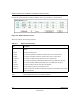
Reference Manual for the MR814 v3 Cable/DSL Wireless Router Click on the “Show Statistics” button to display router usage statistics, as shown below. Figure 6-3: Router Statistics screen This screen shows the following statistics: Table 6-3: Router Statistics Items Item Description Port The statistics for the WAN (Internet) and LAN (local) ports. For each port, the screen displays: Status The link status of the port.
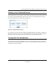
Reference Manual for the MR814 v3 Cable/DSL Wireless Router Viewing a List of Attached Devices The Attached Devices menu contains a table of all IP devices that the router has discovered on the local network. From the Main Menu of the browser interface, under the Maintenance heading, select Attached Devices to view the table, shown below. Figure 6-4: Attached Devices menu For each device, the table shows the IP address, NetBIOS Host Name (if available), and Ethernet MAC address.
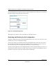
Reference Manual for the MR814 v3 Cable/DSL Wireless Router From the Main Menu of the browser interface, under the Maintenance heading, select the Settings Backup heading to bring up the menu shown below. Figure 6-5: Settings Backup menu Three options are available, and are described in the following sections. Restoring and Backing Up the Configuration The Restore and Backup options in the Settings Backup menu allow you to save and retrieve a file containing your router’s configuration settings.
Reference Manual for the MR814 v3 Cable/DSL Wireless Router Erasing the Configuration It is sometimes desirable to restore the router to a known blank condition. This can be done by using the Erase function, which will restore all factory settings. After an erase, the router's password will be password, the LAN IP address will be 192.168.0.1, and the router's DHCP client will be enabled. To erase the configuration, click the Erase button.
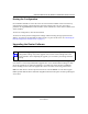
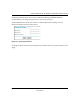
Reference Manual for the MR814 v3 Cable/DSL Wireless Router From the Main Menu of the browser interface, under the Maintenance heading, select the Router Upgrade heading to display the menu shown below. Figure 6-6: Router Upgrade menu To upload new firmware: 1. Download and unzip the new software file from NETGEAR. 2. In the Router Upgrade menu, click the Browse button and browse to the location of the binary (.BIN) upgrade file 3. Click Upload.
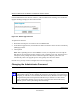
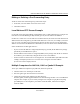
Reference Manual for the MR814 v3 Cable/DSL Wireless Router The default password for the router’s Web Configuration Manager is password. Netgear recommends that you change this password to a more secure password. From the Main Menu of the browser interface, under the Maintenance heading, select Set Password to bring up the menu shown below. Figure 6-7: Set Password menu To change the password, first enter the old password, and then enter the new password twice. Click Apply.
Reference Manual for the MR814 v3 Cable/DSL Wireless Router 6-10 Maintenance 202-10039-01
Chapter 7 Advanced Configuration of the Router This chapter describes how to configure the advanced features of your MR814 v3 Cable/DSL Wireless Router. These features can be found under the Advanced heading in the Main Menu of the browser interface. Configuring for Port Forwarding to Local Servers Although the router causes your entire local network to appear as a single machine to the Internet, you can make a local server (for example, a web server or game server) visible and available to the Internet.
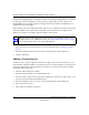
Reference Manual for the MR814 v3 Cable/DSL Wireless Router Use the Port Forwarding menu to configure the router to forward incoming protocols to computers on your local network. In addition to servers for specific applications, you can also specify a Default DMZ Server to which all other incoming protocols are forwarded. The DMZ Server is configured in the Security Menu.
Reference Manual for the MR814 v3 Cable/DSL Wireless Router Editing or Deleting a Port Forwarding Entry To edit or delete a Port Forwarding entry, follow these steps. 1. In the table, select the button next to the service name. 2. Click Edit or Delete. Local Web and FTP Server Example If a local PC with a private IP address of 192.168.0.33 acts as a Web and FTP server, configure the Ports menu to forward HTTP (port 80) and FTP (port 21) to local address 192.168.0.
Reference Manual for the MR814 v3 Cable/DSL Wireless Router 4. Type the same port number in the End Port box that you typed in the Start Port box. 5. Type the IP address of the additional computer in the Server IP Address box. 6. Click Apply. Some online games and videoconferencing applications are incompatible with NAT. The MR814 v3 router is programmed to recognize some of these applications and to work properly with them, but there are other applications that may not function well.
Reference Manual for the MR814 v3 Cable/DSL Wireless Router The WAN Setup menu, shown below lets you configure a Default DMZ Server. Figure 7-2: WAN Setup menu. To assign a computer or server to be a Default DMZ server, follow these steps: Click WAN Setup link on the Advanced section of the main menu. Type the IP address for that server. To remove the default DMZ server, replace the IP address numbers with all zeros. 3. Click Apply. 1. 2.
Reference Manual for the MR814 v3 Cable/DSL Wireless Router Using the LAN IP Setup Options The second feature category under the Advanced heading is LAN IP Setup. This menu allows configuration of LAN IP services such as DHCP and RIP. From the Main Menu of the browser interface, under Advanced, click on LAN IP Setup to view the LAN IP Setup menu, shown below.
Reference Manual for the MR814 v3 Cable/DSL Wireless Router These addresses are part of the IETF-designated private address range for use in private networks, and should be suitable in most applications. If your network has a requirement to use a different IP addressing scheme, you can make those changes in this menu. The LAN IP parameters are: • IP Address This is the LAN IP address of the router. • IP Subnet Mask This is the LAN Subnet Mask of the router.
Reference Manual for the MR814 v3 Cable/DSL Wireless Router Using the Router as a DHCP server By default, the router will function as a DHCP (Dynamic Host Configuration Protocol) server, allowing it to assign IP, DNS server, and default gateway addresses to all computers connected to the router's LAN. The assigned default gateway address is the LAN address of the router. IP addresses will be assigned to the attached PCs from a pool of addresses specified in this menu.
Reference Manual for the MR814 v3 Cable/DSL Wireless Router 2. In the IP Address box, type the IP address to assign to the PC or server. (choose an IP address from the router’s LAN subnet, such as 192.168.0.X) 3. Type the MAC Address of the PC or server. (Tip: If the PC is already present on your network, you can copy its MAC address from the Attached Devices menu and paste it here.) 4. Click Apply to enter the reserved address into the table.
Reference Manual for the MR814 v3 Cable/DSL Wireless Router 2. Select the Use a dynamic DNS service check box. 3. Select the name of your dynamic DNS Service Provider. 4. Type the Host Name (or domain name) that your dynamic DNS service provider gave you. 5. Type the User Name for your dynamic DNS account. 6. Type the Password (or key) for your dynamic DNS account. 7.
Reference Manual for the MR814 v3 Cable/DSL Wireless Router 1. Click the Add button to open the Add/Edit Menu, shown below. Figure 7-5. Static Route Entry and Edit Menu 2. Type a route name for this static route in the Route Name box under the table. (This is for identification purpose only.) 3. Select Private if you want to limit access to the LAN only. The static route will not be reported in RIP. 4. Select Active to make this route effective. 5.
Reference Manual for the MR814 v3 Cable/DSL Wireless Router When you first configured your router, two implicit static routes were created. A default route was created with your ISP as the gateway, and a second static route was created to your local network for all 192.168.0.x addresses. With this configuration, if you attempt to access a device on the 134.177.0.0 network, your router will forward your request to the ISP.
Reference Manual for the MR814 v3 Cable/DSL Wireless Router 3. b. To allow access from a range of IP addresses on the Internet, select IP address range. Enter a beginning and ending IP address to define the allowed range. c. To allow access from a single IP address on the Internet, select Only this PC. Enter the IP address that will be allowed access. Specify the Port Number that will be used for accessing the management interface. Web browser access normally uses the standard HTTP service port 80.
Reference Manual for the MR814 v3 Cable/DSL Wireless Router From the Main Menu of the browser interface, under Advanced, click on UPnP. Set up UPnP according to the guidelines below. Turn UPnP On: UPnP can be enabled or disabled for automatic device configuration. The default setting for UPnP is disabled. If disabled, the router will not allow any device to automatically control the resources, such as port forwarding (mapping), of the router.
Chapter 8 Troubleshooting This chapter gives information about troubleshooting your MR814 v3 Cable/DSL Wireless Router. After each problem description, instructions are provided to help you diagnose and solve the problem. Basic Functioning After you turn on power to the router, the following sequence of events should occur: 1. When power is first applied, verify that the Power light 2. After approximately 10 seconds, verify that: is on. a. The power light is solid green. b.
Reference Manual for the MR814 v3 Cable/DSL Wireless Router Lights Never Turn Off When the router is turned on, the lights turns on for about 10 seconds and then turn off. If all the lights stay on, there is a fault within the router. If all lights are still on one minute after power up: • Cycle the power to see if the router recovers. • Clear the router’s configuration to factory defaults. This will set the router’s IP address to 192.168.0.1.
Reference Manual for the MR814 v3 Cable/DSL Wireless Router Troubleshooting the Web Configuration Interface If you are unable to access the router’s web Configuration interface from a computer on your local network, check the following: • Check the Ethernet connection between the computer and the router as described in the previous section. • Make sure your computer’s IP address is on the same subnet as the router.
Reference Manual for the MR814 v3 Cable/DSL Wireless Router Troubleshooting the ISP Connection If your router is unable to access the Internet, you should first determine whether the router is able to obtain a WAN IP address from the ISP. Unless you have been assigned a static IP address, your router must request an IP address from the ISP. You can determine whether the request was successful using the web Configuration Manager. To check the WAN IP address: 1.
Reference Manual for the MR814 v3 Cable/DSL Wireless Router Inform your ISP that you have bought a new network device, and ask them to use the router’s MAC address. OR Configure your router to spoof your computer’s MAC address. This can be done in the Basic Settings menu. Refer to “How to Bypass the Configuration Assistant” on page 3-12. If your router can obtain an IP address, but your computer is unable to load any web pages from the Internet: • Your computer may not recognize any DNS server addresses.
Reference Manual for the MR814 v3 Cable/DSL Wireless Router 3. Click on OK. You should see a message like this one: Pinging with 32 bytes of data If the path is working, you see this message: Reply from < IP address >: bytes=32 time=NN ms TTL=xxx If the path is not working, you see this message: Request timed out If the path is not functioning correctly, you could have one of the following problems: • Wrong physical connections — Make sure the LAN port LED is on.
Reference Manual for the MR814 v3 Cable/DSL Wireless Router — Check to see that the network address of your computer (the portion of the IP address specified by the netmask) is different from the network address of the remote device. — Check that your cable or DSL modem is connected and functioning. — If your ISP assigned a host name to your computer, enter that host name as the Account Name in the Basic Settings menu.
Reference Manual for the MR814 v3 Cable/DSL Wireless Router Problems with Date and Time The E-Mail menu in the Content Filtering section displays the current date and time of day. The MR814 v3 router uses the Network Time Protocol (NTP) to obtain the current time from one of several Network Time Servers on the Internet. Each entry in the log is stamped with the date and time of day. Problems with the date and time function can include: • Date shown is January 1, 2000.
Appendix A Technical Specifications This appendix provides technical specifications for the MR814 v3 Cable/DSL Wireless Router.
Reference Manual for the MR814 v3 Cable/DSL Wireless Router VCCI Class B EN 55 022 (CISPR 22), Class B Interface Specifications LAN: 10BASE-T or 100BASE-Tx, RJ-45 WAN: 10BASE-T, RJ-45 Wireless Radio Data Rate 1, 2, 5.5, 11Mbps Auto Rate Sensing Frequency 2.4-2.5Ghz Data Encoding: Direct Sequence Spread Spectrum (DSSS) 802.11b Operating Range @ 11 Mbps @ 5.
Appendix B Network, Routing, Firewall, and Basics This chapter provides an overview of IP networks, routing, and networking. Related Publications As you read this document, you may be directed to various RFC documents for further information. An RFC is a Request For Comment (RFC) published by the Internet Engineering Task Force (IETF), an open organization that defines the architecture and operation of the Internet.
Reference Manual for the MR814 v3 Cable/DSL Wireless Router Routing Information Protocol One of the protocols used by a router to build and maintain a picture of the network is the Routing Information Protocol (RIP). Using RIP, routers periodically update one another and check for changes to add to the routing table. The MR814 v3 router supports both the older RIP-1 and the newer RIP-2 protocols. Among other improvements, RIP-2 supports subnet and multicast protocols.
Reference Manual for the MR814 v3 Cable/DSL Wireless Router Class A Network Node Class B Network Node Class C Network Node 7261 Figure B-1: Three Main Address Classes The five address classes are: • Class A Class A addresses can have up to 16,777,214 hosts on a single network. They use an eight-bit network number and a 24-bit node number. Class A addresses are in this range: 1.x.x.x to 126.x.x.x. • Class B Class B addresses can have up to 65,354 hosts on a network.
Reference Manual for the MR814 v3 Cable/DSL Wireless Router This addressing structure allows IP addresses to uniquely identify each physical network and each node on each physical network. For each unique value of the network portion of the address, the base address of the range (host address of all zeros) is known as the network address and is not usually assigned to a host.
Reference Manual for the MR814 v3 Cable/DSL Wireless Router Subnet addressing allows us to split one IP network address into smaller multiple physical networks known as subnetworks. Some of the node numbers are used as a subnet number instead. A Class B address gives us 16 bits of node numbers translating to 64,000 nodes. Most organizations do not use 64,000 nodes, so there are free bits that can be reassigned. Subnet addressing makes use of those bits that are free, as shown below.
Reference Manual for the MR814 v3 Cable/DSL Wireless Router The following table lists the additional subnet mask bits in dotted-decimal notation. To use the table, write down the original class netmask and replace the 0 value octets with the dotted-decimal value of the additional subnet bits. For example, to partition your Class C network with subnet mask 255.255.255.0 into 16 subnets (4 bits), the new subnet mask becomes 255.255.255.240. Table 8-1.
Reference Manual for the MR814 v3 Cable/DSL Wireless Router • So that hosts recognize local IP broadcast packets When a device broadcasts to its segment neighbors, it uses a destination address of the local network address with all ones for the host address. In order for this scheme to work, all devices on the segment must agree on which bits comprise the host address.
Reference Manual for the MR814 v3 Cable/DSL Wireless Router The following figure illustrates a single IP address operation. Private IP addresses assigned by user IP addresses assigned by ISP 192.168.0.2 192.168.0.3 192.168.0.1 172.21.15.105 Internet 192.168.0.4 192.168.0.
Reference Manual for the MR814 v3 Cable/DSL Wireless Router If a device sends data to another station on the network and the destination MAC address is not yet recorded, ARP is used. An ARP request is broadcast onto the network. All stations on the network receive and read the request. The destination IP address for the chosen station is included as part of the message so that only the station with this IP address responds to the ARP request. All other stations discard the request.
Reference Manual for the MR814 v3 Cable/DSL Wireless Router IP Configuration by DHCP When an IP-based local area network is installed, each computer must be configured with an IP address. If the computers need to access the Internet, they should also be configured with a gateway address and one or more DNS server addresses. As an alternative to manual configuration, there is a method by which each computer on the network can automatically obtain this configuration information.
Reference Manual for the MR814 v3 Cable/DSL Wireless Router Stateful Packet Inspection Unlike simple Internet sharing routers, a firewall uses a process called stateful packet inspection to ensure secure firewall filtering to protect your network from attacks and intrusions. Since user-level applications such as FTP and web browsers can create complex patterns of network traffic, it is necessary for the firewall to analyze groups of network connection states.
Reference Manual for the MR814 v3 Cable/DSL Wireless Router Table B-1. UTP Ethernet cable wiring, straight-through Pin Wire color Signal 1 Orange/White Transmit (Tx) + 2 Orange Transmit (Tx) - 3 Green/White Receive (Rx) + 4 Blue 5 Blue/White 6 Green 7 Brown/White 8 Brown Receive (Rx) - Category 5 Cable Quality Category 5 distributed cable that meets ANSI/EIA/TIA-568-A building wiring standards can be a maximum of 328 feet (ft.
Reference Manual for the MR814 v3 Cable/DSL Wireless Router Inside Twisted Pair Cables For two devices to communicate, the transmitter of each device must be connected to the receiver of the other device. The crossover function is usually implemented internally as part of the circuitry in the device. Computers and workstation adapter cards are usually media-dependent interface ports, called MDI or uplink ports.
Reference Manual for the MR814 v3 Cable/DSL Wireless Router Figure B-6: Category 5 UTP Cable with Male RJ-45 Plug at Each End Note: Flat “silver satin” telephone cable may have the same RJ-45 plug. However, using telephone cable results in excessive collisions, causing the attached port to be partitioned or disconnected from the network.
Reference Manual for the MR814 v3 Cable/DSL Wireless Router The MR814 v3 router incorporates Auto UplinkTM technology (also called MDI/MDIX). Each LOCAL Ethernet port will automatically sense whether the Ethernet cable plugged into the port should have a normal connection (e.g. connecting to a computer) or an uplink connection (e.g. connecting to a router, switch, or hub). That port will then configure itself to the correct configuration.
Reference Manual for the MR814 v3 Cable/DSL Wireless Router B-16 Network, Routing, Firewall, and Basics 202-10039-01
Appendix C Preparing Your Network This appendix describes how to prepare your network to connect to the Internet through the MR814 v3 Cable/DSL Wireless Router and how to verify the readiness of broadband Internet service from an Internet service provider (ISP).
Reference Manual for the MR814 v3 Cable/DSL Wireless Router For the initial setup of your router, you will need to connect a computer to the router. This computer has to be set to automatically get its TCP/IP configuration from the router via DHCP. Note: For help with DHCP configuration, please use the Windows TCP/IP Configuration Tutorials on the MR814 v3 Resource CD (2230-10095-01 ), or in this appendix.
Reference Manual for the MR814 v3 Cable/DSL Wireless Router Record Your Internet Connection Information Print this page. Fill in the configuration parameters from your Internet Service Provider (ISP). ISP Login Name: The login name and password are case sensitive and must be entered exactly as given by your ISP. Some ISPs use your full e-mail address as the login name. The Service Name is not required by all ISPs.
Reference Manual for the MR814 v3 Cable/DSL Wireless Router Most operating systems include the software components you need for networking with TCP/IP: • Windows® 95 or later includes the software components for establishing a TCP/IP network. • Windows 3.1 does not include a TCP/IP component. You need to purchase a third-party TCP/ IP application package such as NetManage Chameleon. • Macintosh Operating System 7 or later includes the software components for establishing a TCP/IP network.
Reference Manual for the MR814 v3 Cable/DSL Wireless Router The Network window opens, which displays a list of installed components: You must have an Ethernet adapter, the TCP/IP protocol, and Client for Microsoft Networks. Note: It is not necessary to remove any other network components shown in the Network window in order to install the adapter, TCP/IP, or Client for Microsoft Networks. If you need to install a new adapter, follow these steps: a. Click the Add button. b.
Reference Manual for the MR814 v3 Cable/DSL Wireless Router d. Select TCP/IP, and then click OK. If you need Client for Microsoft Networks: 3. a. Click the Add button. b. Select Client, and then click Add. c. Select Microsoft. d. Select Client for Microsoft Networks, and then click OK. Restart your PC for the changes to take effect.
Reference Manual for the MR814 v3 Cable/DSL Wireless Router Locate your Network Neighborhood icon. • If the Network Neighborhood icon is on the Windows desktop, position your mouse pointer over it and right-click your mouse button. • If the icon is not on the desktop, • Click Start on the task bar located at the bottom left of the window. • Choose Settings, and then Control Panel. • Locate the Network Neighborhood icon and click on it. This will open the Network panel as shown below.
Reference Manual for the MR814 v3 Cable/DSL Wireless Router • By default, the IP Address tab is open on this window. • Verify the following: Obtain an IP address automatically is selected. If not selected, click in the radio button to the left of it to select it. This setting is required to enable the DHCP server to automatically assign an IP address. • Click OK to continue. Restart the PC. Repeat these steps for each PC with this version of Windows on your network.
Reference Manual for the MR814 v3 Cable/DSL Wireless Router 2. Type winipcfg, and then click OK. The IP Configuration window opens, which lists (among other things), your IP address, subnet mask, and default gateway. 3. From the drop-down box, select your Ethernet adapter. The window is updated to show your settings, which should match the values below if you are using the default TCP/IP settings that NETGEAR recommends for connecting through a router or gateway: • The IP address is between 192.168.0.
Reference Manual for the MR814 v3 Cable/DSL Wireless Router DHCP Configuration of TCP/IP in Windows XP, 2000, or NT4 You will find there are many similarities in the procedures for different Windows systems when using DHCP to configure TCP/IP. The following steps will walk you through the configuration process for each of these versions of Windows. DHCP Configuration of TCP/IP in Windows XP Locate your Network Neighborhood icon. • Select Control Panel from the Windows XP new Start Menu.
Reference Manual for the MR814 v3 Cable/DSL Wireless Router • Now you should be at the Local Area Network Connection Status window. This box displays the connection status, duration, speed, and activity statistics. • Administrator logon access rights are needed to use this window. • Click the Properties button to view details about the connection. • The TCP/IP details are presented on the Support tab page. • Select Internet Protocol, and click Properties to view the configuration information.
Reference Manual for the MR814 v3 Cable/DSL Wireless Router • Verify that the Obtain an IP address automatically radio button is selected. • Verify that Obtain DNS server address automatically radio button is selected. • Click the OK button. This completes the DHCP configuration of TCP/ IP in Windows XP. Repeat these steps for each PC with this version of Windows on your network.
Reference Manual for the MR814 v3 Cable/DSL Wireless Router • Click on the My Network Places icon on the Windows desktop. This will bring up a window called Network and Dial-up Connections. • Right click on Local Area Connection and select Properties. • The Local Area Connection Properties dialog box appears. • Verify that you have the correct Ethernet card selected in the Connect using: box.
Reference Manual for the MR814 v3 Cable/DSL Wireless Router • With Internet Protocol (TCP/IP) selected, click on Properties to open the Internet Protocol (TCP/IP) Properties dialogue box. • Verify that • Obtain an IP address automatically is selected. • Obtain DNS server address automatically is selected. • Click OK to return to Local Area Connection Properties. • Click OK again to complete the configuration process for Windows 2000. Restart the PC.
Reference Manual for the MR814 v3 Cable/DSL Wireless Router DHCP Configuration of TCP/IP in Windows NT4 Once you have installed the network card, you need to configure the TCP/IP environment for Windows NT 4.0. Follow this procedure to configure TCP/IP with DHCP in Windows NT 4.0. • Choose Settings from the Start Menu, and then select Control Panel. This will display Control Panel window. • Double-click the Network icon in the Control Panel window. The Network panel will display.
Reference Manual for the MR814 v3 Cable/DSL Wireless Router • Highlight the TCP/IP Protocol in the Network Protocols box, and click on the Properties button.
Reference Manual for the MR814 v3 Cable/DSL Wireless Router • The TCP/IP Properties dialog box now displays. • Click the IP Address tab. • Select the radio button marked Obtain an IP address from a DHCP server. • Click OK. This completes the configuration of TCP/IP in Windows NT. Restart the PC. Repeat these steps for each PC with this version of Windows on your network. Verifying TCP/IP Properties for Windows XP, 2000, and NT4 To check your PC’s TCP/IP configuration: 1.
Reference Manual for the MR814 v3 Cable/DSL Wireless Router • 4. The default gateway is 192.168.0.1 Type exit Configuring the Macintosh for TCP/IP Networking Beginning with Macintosh Operating System 7, TCP/IP is already installed on the Macintosh. On each networked Macintosh, you will need to configure TCP/IP to use DHCP. MacOS 8.6 or 9.x 1. From the Apple menu, select Control Panels, then TCP/IP. The TCP/IP Control Panel opens: 2.
Reference Manual for the MR814 v3 Cable/DSL Wireless Router 2. If not already selected, select Built-in Ethernet in the Configure list. 3. If not already selected, Select Using DHCP in the TCP/IP tab. 4. Click Save. Verifying TCP/IP Properties for Macintosh Computers After your Macintosh is configured and has rebooted, you can check the TCP/IP configuration by returning to the TCP/IP Control Panel. From the Apple menu, select Control Panels, then TCP/IP.
Reference Manual for the MR814 v3 Cable/DSL Wireless Router Verifying the Readiness of Your Internet Account For broadband access to the Internet, you need to contract with an Internet service provider (ISP) for a single-user Internet access account using a cable modem or DSL modem. This modem must be a separate physical box (not a card) and must provide an Ethernet port intended for connection to a Network Interface Card (NIC) in a computer. Your firewall does not support a USB-connected broadband modem.
Reference Manual for the MR814 v3 Cable/DSL Wireless Router • An IP address and subnet mask • A gateway IP address, which is the address of the ISP’s router • One or more domain name server (DNS) IP addresses • Host name and domain suffix For example, your account’s full server names may look like this: mail.xxx.yyy.com In this example, the domain suffix is xxx.yyy.com. If any of these items are dynamically supplied by the ISP, your firewall automatically acquires them.
Reference Manual for the MR814 v3 Cable/DSL Wireless Router If an IP address appears under Installed Gateways, write down the address. This is the ISP’s gateway address. Select the address and then click Remove to remove the gateway address. 6. Select the DNS Configuration tab. If any DNS server addresses are shown, write down the addresses. If any information appears in the Host or Domain information box, write it down. Click Disable DNS. 7.
Reference Manual for the MR814 v3 Cable/DSL Wireless Router Restarting the Network Once you’ve set up your computers to work with the firewall, you must reset the network for the devices to be able to communicate correctly. Restart any computer that is connected to the firewall. After configuring all of your computers for TCP/IP networking and restarting them, and connecting them to the local network of your MR814 v3 router, you are ready to access and configure the firewall.
Reference Manual for the MR814 v3 Cable/DSL Wireless Router C-24 Preparing Your Network 202-10039-01
Appendix D Wireless Networking Basics This chapter provides an overview of Wireless networking. Wireless Networking Overview The MR814 v3 router conforms to the Institute of Electrical and Electronics Engineers (IEEE) 802.11b standard for wireless LANs (WLANs). On an 802.11b wireless link, data is encoded using direct-sequence spread-spectrum (DSSS) technology and is transmitted in the unlicensed radio spectrum at 2.5GHz.
Reference Manual for the MR814 v3 Cable/DSL Wireless Router Ad Hoc Mode (Peer-to-Peer Workgroup) In an ad hoc network, computers are brought together as needed; thus, there is no structure or fixed points to the network - each node can generally communicate with any other node. There is no Access Point involved in this configuration.
Reference Manual for the MR814 v3 Cable/DSL Wireless Router The radio frequency channels used are listed in Table 8-3: Table 8-3. 802.11 Radio Frequency Channels Channel Center Frequency Frequency Spread 1 2412 MHz 2399.5 MHz - 2424.5 MHz 2 2417 MHz 2404.5 MHz - 2429.5 MHz 3 2422 MHz 2409.5 MHz - 2434.5 MHz 4 2427 MHz 2414.5 MHz - 2439.5 MHz 5 2432 MHz 2419.5 MHz - 2444.5 MHz 6 2437 MHz 2424.5 MHz - 2449.5 MHz 7 2442 MHz 2429.5 MHz - 2454.5 MHz 8 2447 MHz 2434.5 MHz - 2459.
Reference Manual for the MR814 v3 Cable/DSL Wireless Router Authentication and WEP The absence of a physical connection between nodes makes the wireless links vulnerable to eavesdropping and information theft. To provide a certain level of security, the IEEE 802.11 standard has defined two types of authentication methods, Open System and Shared Key. With Open System authentication, a wireless PC can join any network and receive any messages that are not encrypted.
Reference Manual for the MR814 v3 Cable/DSL Wireless Router • Shared Key Authentication requires that the station and the access point have the same WEP Key to authenticate. These two authentication procedures are described below. Open System Authentication The following steps occur when two devices use Open System Authentication: 1. The station sends an authentication request to the access point. 2. The access point authenticates the station. 3.
Reference Manual for the MR814 v3 Cable/DSL Wireless Router 5. The station connects to the network. If the decrypted text does not match the original challenge text (i.e., the access point and station do not share the same WEP Key), then the access point will refuse to authenticate the station and the station will be unable to communicate with either the 802.11b network or Ethernet network. This process is illustrated in below. 802.
Reference Manual for the MR814 v3 Cable/DSL Wireless Router 3. Use WEP for Authentication and Encryption: A transmitting 802.11b device encrypts the data portion of every packet it sends using a configured WEP Key. The receiving 802.11b device decrypts the data using the same WEP Key. For authentication purposes, the 802.11b network uses Shared Key Authentication. Note: Some 802.11b access points also support Use WEP for Authentication Only (Shared Key Authentication without data encryption).
Reference Manual for the MR814 v3 Cable/DSL Wireless Router WEP Configuration Options The WEP settings must match on all 802.11b devices that are within the same wireless network as identified by the SSID. In general, if your mobile clients will roam between access points, then all of the 802.11b access points and all of the 802.11b client adapters on the network must have the same WEP settings.
Reference Manual for the MR814 v3 Cable/DSL Wireless Router The Wi-Fi Alliance is now performing interoperability certification testing on Wi-Fi Protected Access products. Starting August of 2003, all new Wi-Fi certified products will have to support WPA. NETGEAR will implement WPA on client and access point products and make this available in the second half of 2003. Existing Wi-Fi certified products will have one year to add WPA support or they will loose their Wi-Fi certification. The 802.
Reference Manual for the MR814 v3 Cable/DSL Wireless Router How Does WPA Compare to IEEE 802.11i? WPA will be forward compatible with the IEEE 802.11i security specification currently under development. WPA is a subset of the current 802.11i draft and uses certain pieces of the 802.11i draft that are ready to bring to market today, such as 802.1x and TKIP. The main pieces of the 802.11i draft that are not included in WPA are secure IBSS (Ad-Hoc mode), secure fast handoff (for specialized 802.
Reference Manual for the MR814 v3 Cable/DSL Wireless Router The primary information conveyed in the Beacon frames is the authentication method and the cipher suite. Possible authentication methods include 802.1X and Pre-shared key. Pre-shared key is an authentication method that uses a statically configured pass phrase on both the stations and the access point. This obviates the need for an authentication server, which in many home and small office environments will not be available nor desirable.
Reference Manual for the MR814 v3 Cable/DSL Wireless Router WPA Authentication: Enterprise-level User Authentication via 802.1x/EAP and RADIUS Wireless LAN WPA enabled wireless client with “supplicant” WPA enabled Access Point using pre-shared key or 802.1x Wired Network with Optional 802.
Reference Manual for the MR814 v3 Cable/DSL Wireless Router Client with a WPAenabled wireless adapter and supplicant (Win XP, Funk, Meetinghouse, etc.) For example, a RADIUS server For example, a WPA-enabled AP 1 2 3 4 6 5 7 Figure D-2: 802.1x Authentication Sequence The AP sends Beacon Frames with WPA information element to the stations in the service set. Information elements include the required authentication method (802.1x or Pre-shared key) and the preferred cipher suite (WEP, TKIP, or AES).
Reference Manual for the MR814 v3 Cable/DSL Wireless Router 3. The client sends an EAP-response packet containing the identity to the authentication server. The access point responds by enabling a port for passing only EAP packets from the client to an authentication server located on the wired side of the access point. The access point blocks all other traffic, such as HTTP, DHCP, and POP3 packets, until the access point can verify the client's identity using an authentication server (e.g., RADIUS). 4.
Reference Manual for the MR814 v3 Cable/DSL Wireless Router Temporal Key Integrity Protocol (TKIP) WPA uses TKIP to provide important data encryption enhancements including a per-packet key mixing function, a message integrity check (MIC) named Michael, an extended initialization vector (IV) with sequencing rules, and a re-keying mechanism. TKIP also provides for the following: • • • The verification of the security configuration after the encryption keys are determined.
Reference Manual for the MR814 v3 Cable/DSL Wireless Router Is WPA Perfect? WPA is not without its vulnerabilities. Specifically, it is susceptible to denial of service (DoS) attacks. If the access point receives two data packets that fail the Message Integrity Code (MIC) check within 60 seconds of each other then the network is under an active attack, and as a result, the access point employs counter measures, which includes disassociating each station using the access point.
Reference Manual for the MR814 v3 Cable/DSL Wireless Router • • • • • The new WPA information element To advertise their support of WPA, wireless APs send the beacon frame with a new 802.11 WPA information element that contains the wireless AP's security configuration (encryption algorithms and wireless security configuration information). The WPA two-phase authentication Open system, then 802.1x (EAP with RADIUS or preshared key).
Reference Manual for the MR814 v3 Cable/DSL Wireless Router Changes to Wireless Client Programs Wireless client programs must be updated to permit the configuration of WPA authentication (and preshared key) and the new WPA encryption algorithms (TKIP and the optional AES component). To obtain the Microsoft WPA client program, visit the following Microsoft Web site.
Glossary 10BASE-T IEEE 802.3 specification for 10 Mbps Ethernet over twisted pair wiring. 100BASE-Tx IEEE 802.3 specification for 100 Mbps Ethernet over twisted pair wiring. 802.11b IEEE specification for wireless networking at 11 Mbps using direct-sequence spread-spectrum (DSSS) technology and operating in the unlicensed radio spectrum at 2.5GHz. Denial of Service attack DoS. A hacker attack designed to prevent your computer or network from operating or communicating.
Reference Manual for the MR814 v3 Cable/DSL Wireless Router Internet Protocol The main internetworking protocol used in the Internet. Used in conjunction with the Transfer Control Protocol (TCP) to form TCP/IP. LAN See local area network. local area network LAN. A communications network serving users within a limited area, such as one floor of a building. A LAN typically connects multiple personal computers and shared network devices such as storage and printers.
Reference Manual for the MR814 v3 Cable/DSL Wireless Router Point-to-Point Protocol PPP. A protocol allowing a computer using TCP/IP to connect directly to the Internet. RFC Request For Comment. Refers to documents published by the Internet Engineering Task Force (IETF) proposing standard protocols and procedures for the Internet. RFCs can be found at www.ietf.org. RIP See Routing Information Protocol. router A device that forwards data between networks.
Reference Manual for the MR814 v3 Cable/DSL Wireless Router Glossary 4 202-10039-01
Index Numerics D 802.
front panel 2-6, 2-7 log sending 5-7 fully qualified domain name (FQDN) 4-6 log entries 5-6 Flash memory, for firmware upgrade 2-1 Logout 3-11, 3-12 G gateway address C-22 H Half Life 7-3 host name 3-14 M MAC address 8-7, B-8 spoofing 3-14, 8-5 Macintosh C-21 configuring for IP networking C-18 DHCP Client ID C-18 Obtaining ISP Configuration Information C-22 I masquerading C-20 IANA contacting B-2 MDI/MDI-X wiring B-14 MDI/MDI-X B-15 IETF B-1 Web site address B-7 metric 7-11 infrastructure mo
port filtering 5-3 Secondary DNS Server 3-14 Port Forwarding 7-1 security 2-1, 2-3 port forwarding behind NAT B-8 service numbers 5-4 Port Forwarding Menu 7-1 Setup Wizard 3-1 port numbers 5-3 Shared Key authentication D-4 PPP over Ethernet 2-4, C-20 SMTP 5-8 PPPoE 2-4, C-20 spoof MAC address 8-5 Primary DNS Server 3-14 SSID 2-8, 4-4, 4-9, D-2 protocols Address Resolution B-8 DHCP 2-4, B-10 Routing Information 2-3, B-2 support 2-1 Start Port 7-2 publications, related B-1 subnet addressing
WinPOET C-20 Wired Equivalent Privacy.