
User's Manual
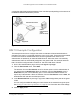
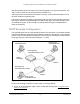

Table Of Contents
- 8-Port Multi-Gigabit Smart Managed Pro Switch with Two 10G Ports
- Contents
- 1 Get Started
- 2 Configure System Information
- View and Configure the Switch Management Settings
- View or Define System Information and View Software Versions
- View the System CPU Status
- View USB Device Information
- Configure the IPv4 Address for the Network Interface and Management VLAN
- Configure the IPv6 Address for the Network Interface
- View the IPv6 Network Neighbor
- Configure the Time Settings
- Configure DNS Settings
- Configure Green Ethernet Settings
- Use the Device View
- Configure Power over Ethernet
- Configure SNMP
- Configure LLDP
- Configure DHCP Snooping
- Set Up PoE Timer Schedules
- View and Configure the Switch Management Settings
- 3 Configure Switching
- Configure Port Settings and Flow Control
- Configure Link Aggregation Groups
- Configure VLANs
- Configure VLAN Settings
- Configure VLAN Membership
- View VLAN Status
- Configure Port PVID Settings
- Configure MAC-Based VLAN Groups
- Manually Add Members to or Remove Them From a MAC-Based VLAN Group
- Configure Protocol-Based VLAN Groups
- Manually Add Members to or Remove Them From a Protocol-Based VLAN Group
- Configure GARP Switch Settings
- Configure GARP Ports
- Configure a Voice VLAN
- Configure Auto-VoIP
- Configure Spanning Tree Protocol
- Configure Multicast
- View the MFDB Table
- View the MFDB Statistics
- Configure Auto-Video
- IGMP Snooping Overview
- Configure the Global IGMP Snooping Settings
- View the IGMP Snooping Table
- Configure IGMP Snooping for VLANs
- Modify IGMP Snooping Settings for a VLAN
- Disable IGMP Snooping on a VLAN and Remove It From the Table
- IGMP Snooping Querier Overview
- Configure IGMP Snooping Querier
- Configure IGMP Snooping Querier for VLANs
- Display the IGMP Snooping Querier for VLAN Status
- MLD Snooping Overview
- Configure the Global MLD Snooping Settings
- Configure MLD Snooping for a VLAN
- View, Search, and Manage the MAC Address Table
- 4 Configure Routing
- IP Routing Overview
- Configure IP Settings
- Configure VLAN Routing
- Manage IPv4 Routes
- Configure Address Resolution Protocol
- Configure IPv6
- Configure IPv6 Global Settings
- Add a Static IPv6 Route
- Change the Preference for a Static IPv6 Route
- Remove a Static IPv6 Route
- View the IPv6 Route Table
- Configure IPv6 VLAN Interface Settings
- Add an IPv6 Global Address to an IPv6 VLAN
- Change the Settings for an IPv6 Global Address on an IPv6 VLAN
- Remove an IPv6 Global Address From an IPv6 VLAN
- Add an IPv6 Prefix for Advertisement on an IPv6 VLAN
- Change the Settings for an IPv6 Prefix for Advertisement on an IPv6 VLAN
- Remove an IPv6 Prefix From an IPv6 VLAN
- View IPv6 Statistics for an Interface
- View or Clear the IPv6 Neighbor Table
- 5 Configure Quality of Service
- 6 Manage Device Security
- Management Security Settings
- Configure Management Access
- Configure Port Authentication
- Set Up Traffic Control
- Configure Access Control Lists
- Use the ACL Wizard to Create a Simple ACL
- Configure a Basic MAC ACL
- Configure MAC ACL Rules
- Configure MAC Bindings
- View or Delete MAC ACL Bindings in the MAC Binding Table
- Configure an IP ACL
- Configure Rules for a Basic IP ACL
- Configure Rules for an Extended IP ACL
- Configure an IPv6 ACL
- Configure IPv6 Rules
- Configure IP ACL Interface Bindings
- View or Delete IP ACL Bindings in the IP ACL Binding Table
- 7 Monitor the System
- 8 Maintain the Switch and Perform Troubleshooting
- A Configuration Examples
- B Hardware Specifications and Default Settings

Smart Managed Pro Switches MS510TX and MS510TXPP
Configuration Examples User Manual348
2. On the VLAN Membership page, include ports g1–mg7 as tagged (T) or untagged (U)
members of VLAN 300 and VLAN 500 (see
Configure VLAN Membership on page 99).
3. On the STP Configuration page, enable the Spanning Tree State option (see Configure STP
Settings on page 118).
Use the default values for the rest of the STP configuration settings. By default, the STP
operation mode is MSTP and the configuration name is the switch MAC address.
4. On the CST Configuration page, set the bridge priority value for each of the three switches
to force Switch 1 to be the root bridge:
• Switch 1. 4096
• Switch 2. 12288
• Switch 3. 20480
Note: Bridge priority values are multiples of 4096.
If you do not specify a root bridge and all switches are assigned the same bridge priority
value, the switch with the lowest MAC address is elected as the root bridge (see
Configure CST Settings on page 120).
5. On the CST Port Configuration page, select ports g1–mg7 and select Enable from the STP
Status menu (see
Configure CST Port Settings on page 122).
6. Click the Apply button.
7. Select ports g1–mg5 (edge ports), and select Enable from the Fast Link menu.
Since the edge ports are not at risk for network loops, ports with Fast Link enabled
transition directly to the forwarding state.
8. Click the Apply button.
You can use the CST Port Status page to view spanning tree information about each port.
9. On the MST Configuration page, create a MST instances with the following settings:
• MST ID. 1
• Priority. Use the default (32768)
• VLAN ID. 300
For more information, see Manage MST Settings on page 125.
10. Click the Add button.
11. Create a second MST instance with the following settings
• MST ID. 2
• Priority. 49152
• VLAN ID. 500
12. Click the Add button.
In this example, assume that switch 1 became the root bridge for the MST instance 1, and
switch 2 became the root bridge for MST instance 2. Switch 3 supports hosts in the sales
department (ports g1, g2, and g3) and in the HR department (ports g4 and mg5). Switches 1