
- Netgear ProSafe WFS709TP Smart Wireless Controller Manual


Table Of Contents
- WFS709TP ProSafe Smart Wireless Switch Software Administration Manual
- Contents
- About This Manual
- Chapter 1 Overview of the WFS709TP
- Chapter 2 Deploying a Basic WFS709TP System
- Chapter 3 Configuring Network Parameters
- Chapter 4 RF Plan
- Chapter 5 Configuring WLANS
- Chapter 6 Configuring AAA Servers
- Chapter 7 Configuring 802.1x Authentication
- Chapter 8 Configuring the Captive Portal
- Chapter 9 Configuring MAC-Based Authentication
- Chapter 10 Adding Local WFS709TPs
- Chapter 11 Configuring Redundancy
- Chapter 12 Configuring Wireless Intrusion Protection
- Chapter 13 Configuring Management Utilities
- Chapter 14 Configuring WFS709TP for Voice
- Appendix A Configuring DHCP with Vendor-Specific Options
- Appendix B Windows Client Example Configuration for 802.1x
- Appendix C Internal Captive Portal
- Appendix D Related Documents
- Index
WFS709TP ProSafe Smart Wireless Switch Software Administration Manual
2-2 Deploying a Basic WFS709TP System
v1.0, June 2007
• Set the IP address of VLAN 1.
• Set the default gateway to the IP address of the interface of the upstream router to which
you will connect the WFS709TP.
2. Connect the uplink port on the WFS709TP to the switch or router interface. By default, all
ports on the WFS709TP are access ports and will carry traffic for a single VLAN.
3. Deploy the APs. The APs will use the ADP protocol to locate the WFS709TP.
You would then configure the SSIDs with VLAN 1 as the assigned VLAN for all users.
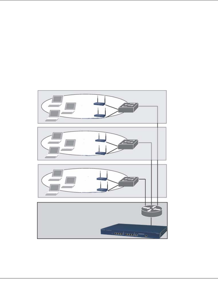
Deployment Scenario #2
Figure 2-2
Data center
Floor 3
subnet
Floor 2
subnet
Floor 1
subnet
WFS709TP
is default
gateway
for clients