
- Netgear ProSafe WFS709TP Smart Wireless Controller Manual


Table Of Contents
- WFS709TP ProSafe Smart Wireless Switch Software Administration Manual
- Contents
- About This Manual
- Chapter 1 Overview of the WFS709TP
- Chapter 2 Deploying a Basic WFS709TP System
- Chapter 3 Configuring Network Parameters
- Chapter 4 RF Plan
- Chapter 5 Configuring WLANS
- Chapter 6 Configuring AAA Servers
- Chapter 7 Configuring 802.1x Authentication
- Chapter 8 Configuring the Captive Portal
- Chapter 9 Configuring MAC-Based Authentication
- Chapter 10 Adding Local WFS709TPs
- Chapter 11 Configuring Redundancy
- Chapter 12 Configuring Wireless Intrusion Protection
- Chapter 13 Configuring Management Utilities
- Chapter 14 Configuring WFS709TP for Voice
- Appendix A Configuring DHCP with Vendor-Specific Options
- Appendix B Windows Client Example Configuration for 802.1x
- Appendix C Internal Captive Portal
- Appendix D Related Documents
- Index
WFS709TP ProSafe Smart Wireless Switch Software Administration Manual
4-12 RF Plan
v1.0, June 2007
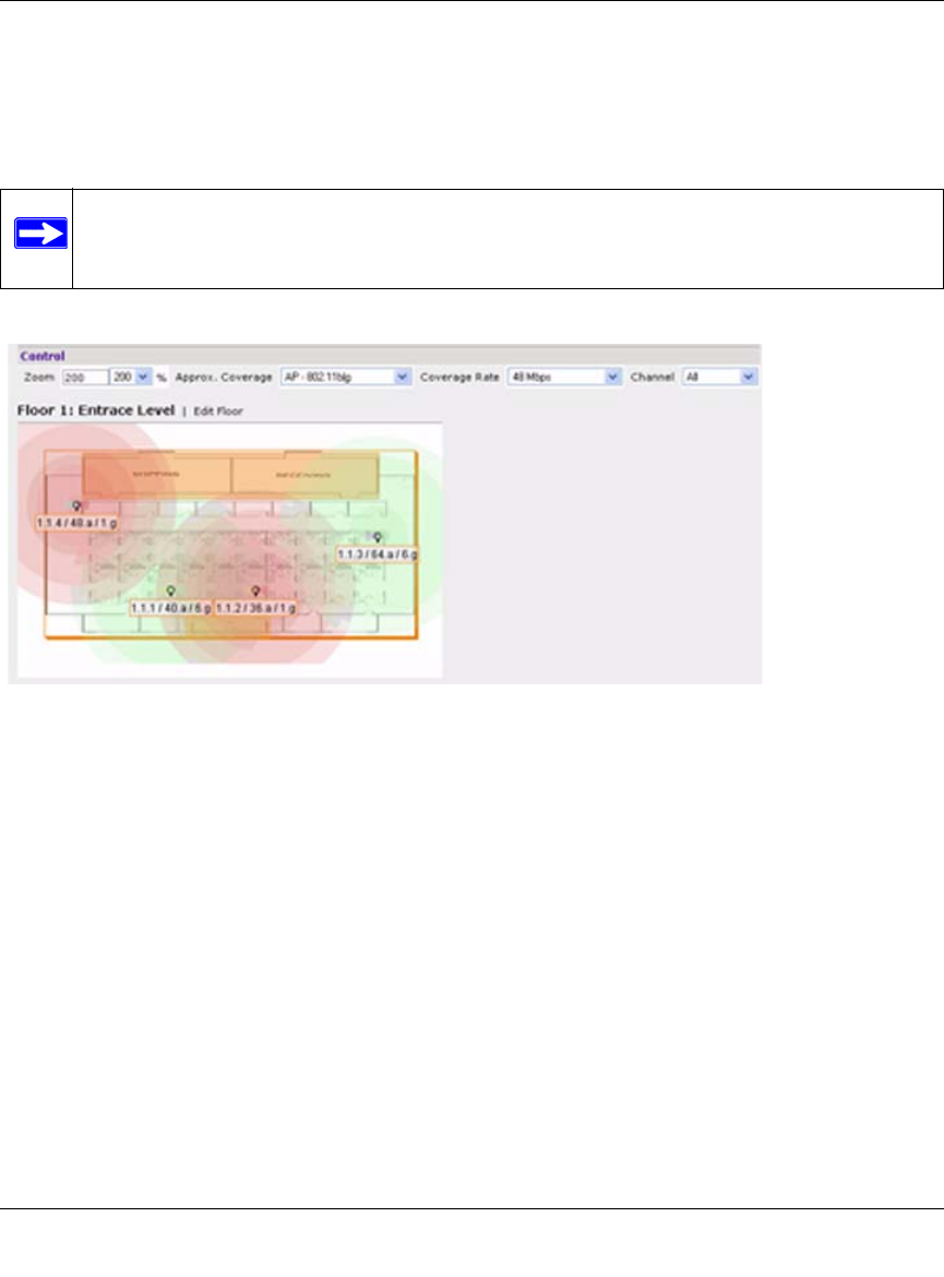
Coverage
Select a radio type from the Coverage pull-down menu to view the approximate coverage area for
each of the APs that RF Plan has deployed in the AP Plan or AM Plan (Figure 4-8). Adjusting the
Coverage values help you to understand how the AP coverage works in your building.
Coverage Rate
Adjusting the coverage rate also affects the size of the coverage areas for AMs. Adjusting the rate
values helps you to understand how the coverage works in your proposed building.
Floor Editor Dialog Box
The Floor Editor dialog box (Figure 4-9) allows you to specify the background image and name
the floor. The Floor Editor is accessible from the Floors Page by clicking on the Edit Floor link.
Note: You will not see coverage areas displayed here until you have executed either an
AP Plan or an AM Plan.
Figure 4-8