
- Netgear ProSafe WFS709TP Smart Wireless Controller Manual


Table Of Contents
- WFS709TP ProSafe Smart Wireless Switch Software Administration Manual
- Contents
- About This Manual
- Chapter 1 Overview of the WFS709TP
- Chapter 2 Deploying a Basic WFS709TP System
- Chapter 3 Configuring Network Parameters
- Chapter 4 RF Plan
- Chapter 5 Configuring WLANS
- Chapter 6 Configuring AAA Servers
- Chapter 7 Configuring 802.1x Authentication
- Chapter 8 Configuring the Captive Portal
- Chapter 9 Configuring MAC-Based Authentication
- Chapter 10 Adding Local WFS709TPs
- Chapter 11 Configuring Redundancy
- Chapter 12 Configuring Wireless Intrusion Protection
- Chapter 13 Configuring Management Utilities
- Chapter 14 Configuring WFS709TP for Voice
- Appendix A Configuring DHCP with Vendor-Specific Options
- Appendix B Windows Client Example Configuration for 802.1x
- Appendix C Internal Captive Portal
- Appendix D Related Documents
- Index
WFS709TP ProSafe Smart Wireless Switch Software Administration Manual
4-14 RF Plan
v1.0, June 2007
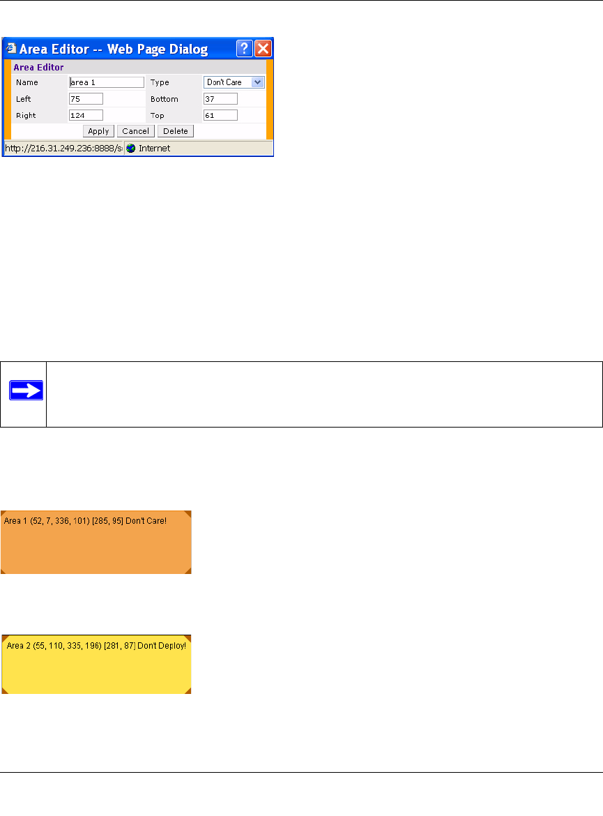
Naming. You can name an area using an alphanumeric string of characters with a maximum
length of 64 characters. Give areas meaningful names so that they are easily identified.
Locating and Sizing. Specify absolute coordinates for the lower left corner and upper right
corner of the box that represents the area you are defining. The datum for measurement is the
lower left corner of the rectangular display area that represents your building’s footprint. The
coordinates of the upper right corner of the display area are the absolute (no unit of measure)
values of the dimensions you gave your building when you defined it with the dimension feature.
Don’t Care areas are displayed as orange rectangles (Figure 4-11) and Don’t Deploy areas are
displayed as yellow rectangles (Figure 4-12). You can drag your defined area to the location where
you want it, and resize it by dragging one or more of the handles in the corners of the rectangle.
Figure 4-10
Note: The location is zero-based. Values range from 0 to (height - 1 and width - 1). For
example, if you defined your building to be 200 feet wide and 400 feet long, the
coordinates of the upper right corner would be (199, 399).
Figure 4-11
Figure 4-12