
- Netgear ProSafe WFS709TP Smart Wireless Controller Manual


Table Of Contents
- WFS709TP ProSafe Smart Wireless Switch Software Administration Manual
- Contents
- About This Manual
- Chapter 1 Overview of the WFS709TP
- Chapter 2 Deploying a Basic WFS709TP System
- Chapter 3 Configuring Network Parameters
- Chapter 4 RF Plan
- Chapter 5 Configuring WLANS
- Chapter 6 Configuring AAA Servers
- Chapter 7 Configuring 802.1x Authentication
- Chapter 8 Configuring the Captive Portal
- Chapter 9 Configuring MAC-Based Authentication
- Chapter 10 Adding Local WFS709TPs
- Chapter 11 Configuring Redundancy
- Chapter 12 Configuring Wireless Intrusion Protection
- Chapter 13 Configuring Management Utilities
- Chapter 14 Configuring WFS709TP for Voice
- Appendix A Configuring DHCP with Vendor-Specific Options
- Appendix B Windows Client Example Configuration for 802.1x
- Appendix C Internal Captive Portal
- Appendix D Related Documents
- Index
WFS709TP ProSafe Smart Wireless Switch Software Administration Manual
RF Plan 4-15
v1.0, June 2007
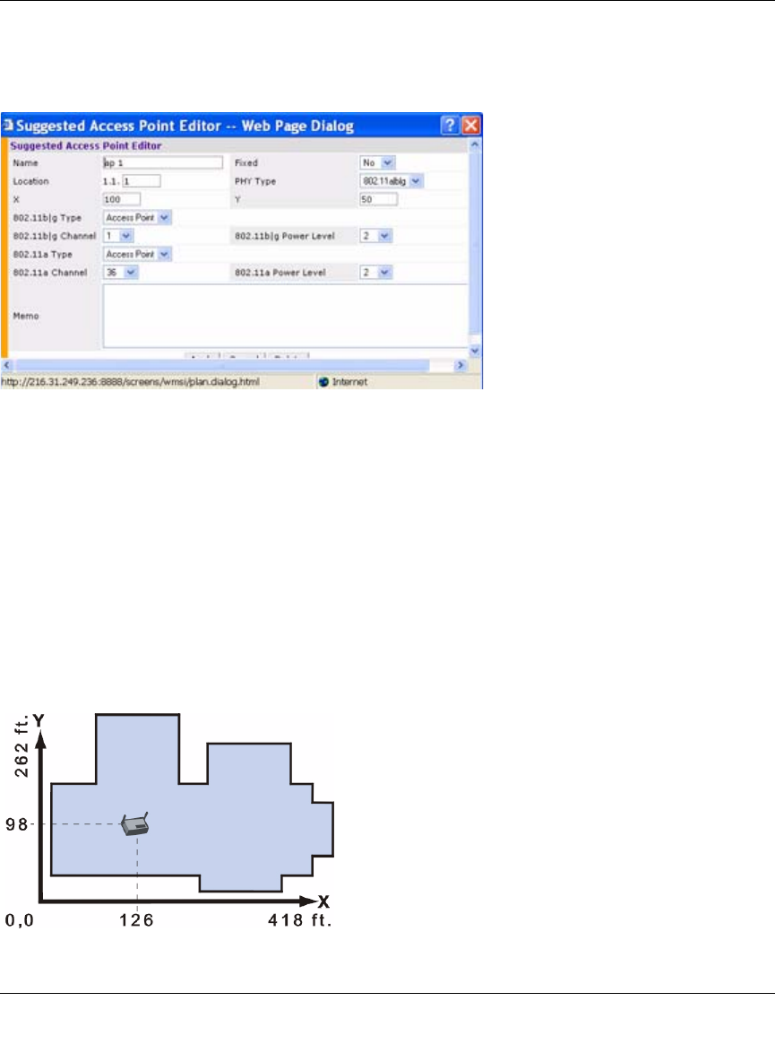
Access Point Editor Page
The Access Point Editor (Figure 4-13) allows you to manually create or modify a suggested AP.
Naming. RF Plan automatically names APs using the default convention ap number, where
number starts at 1 and increments by one for each new AP. When you manually create an AP, the
new AP is assigned the next number and is added to the bottom of the suggested AP list.
You can name an AP anything you wish. The name must consist of alphanumeric characters and be
64 characters or less in length.
X and Y Coordinates. The physical location of the AP is specified by X-Y coordinates that
begin at the lower left corner of the display area, as shown in Figure 4-14. The numbers you
specify in the X and Y text boxes are whole units. The Y coordinate increases as a point moves up
the display, and the X coordinate increases as it moves from left to right across the display.
Figure 4-13
Figure 4-14