
- Netgear ProSafe WFS709TP Smart Wireless Controller Manual


Table Of Contents
- WFS709TP ProSafe Smart Wireless Switch Software Administration Manual
- Contents
- About This Manual
- Chapter 1 Overview of the WFS709TP
- Chapter 2 Deploying a Basic WFS709TP System
- Chapter 3 Configuring Network Parameters
- Chapter 4 RF Plan
- Chapter 5 Configuring WLANS
- Chapter 6 Configuring AAA Servers
- Chapter 7 Configuring 802.1x Authentication
- Chapter 8 Configuring the Captive Portal
- Chapter 9 Configuring MAC-Based Authentication
- Chapter 10 Adding Local WFS709TPs
- Chapter 11 Configuring Redundancy
- Chapter 12 Configuring Wireless Intrusion Protection
- Chapter 13 Configuring Management Utilities
- Chapter 14 Configuring WFS709TP for Voice
- Appendix A Configuring DHCP with Vendor-Specific Options
- Appendix B Windows Client Example Configuration for 802.1x
- Appendix C Internal Captive Portal
- Appendix D Related Documents
- Index
WFS709TP ProSafe Smart Wireless Switch Software Administration Manual
RF Plan 4-25
v1.0, June 2007
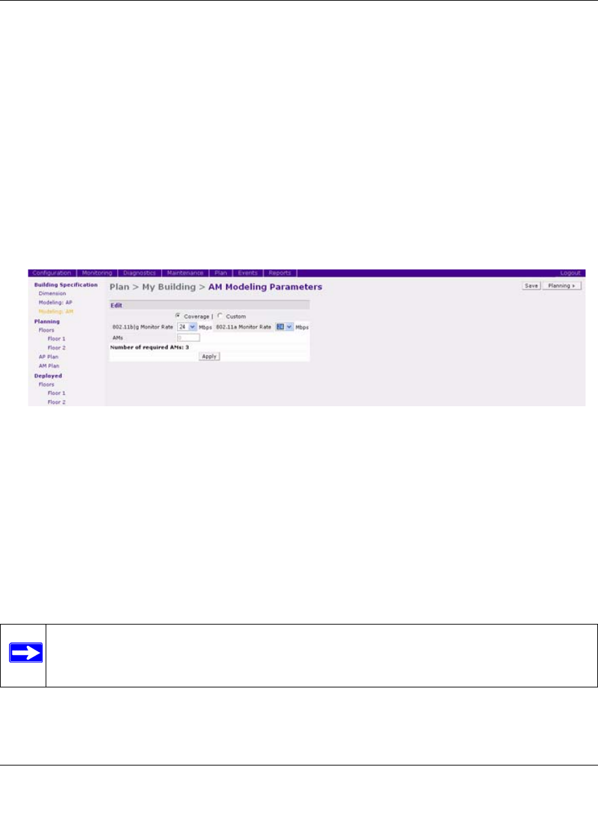
Model the Air Monitors
You now determine how many AMs are required to provide a specified monitoring rate. In this
example you continue to use the Coverage Model and make the following assumptions:
• 802.11 b|g monitor rate: 48 Mbps
• 802.11 a monitor rate: 48 Mbps
To model the air monitors:
1. Select 24 from the 802.11 b|g Monitor Rate drop-down menu.
2. Select 24 from the 802.11 a Monitor Rate drop-down menu.
Notice that the number of required AMs is now 3. (Figure 4-25)
3. Click Save, then Apply.
RF Plan moves to the Planning page.
Add and Edit a Floor
You now add floor plans to your floors (Figure 4-26). In this section you:
• Add a background image floor plan for each floor
• Name the floors
To add the background image and name the first floor:
1. In the Planning page, click the Edit Floor link at the right of the Floor 1 indicator.
Figure 4-25
Note: This section uses example floor plans that are provided with the Windows
application version of RF Plan.