
User's Manual


Table Of Contents
- WFS709TP ProSafe Smart Wireless Switch Software Administration Manual
- Contents
- About This Manual
- Chapter 1 Overview of the WFS709TP
- Chapter 2 Deploying a Basic WFS709TP System
- Chapter 3 Configuring Network Parameters
- Chapter 4 RF Plan
- Chapter 5 Configuring WLANS
- Chapter 6 Configuring AAA Servers
- Chapter 7 Configuring 802.1x Authentication
- Chapter 8 Configuring the Captive Portal
- Chapter 9 Configuring MAC-Based Authentication
- Chapter 10 Adding Local WFS709TPs
- Chapter 11 Configuring Redundancy
- Chapter 12 Configuring Wireless Intrusion Protection
- Chapter 13 Configuring Management Utilities
- Chapter 14 Configuring WFS709TP for Voice
- Appendix A Configuring DHCP with Vendor-Specific Options
- Appendix B Windows Client Example Configuration for 802.1x
- Appendix C Internal Captive Portal
- Appendix D Related Documents
- Index
WFS709TP ProSafe Smart Wireless Switch Software Administration Manual
1-2 Overview of the WFS709TP
v1.0, June 2007
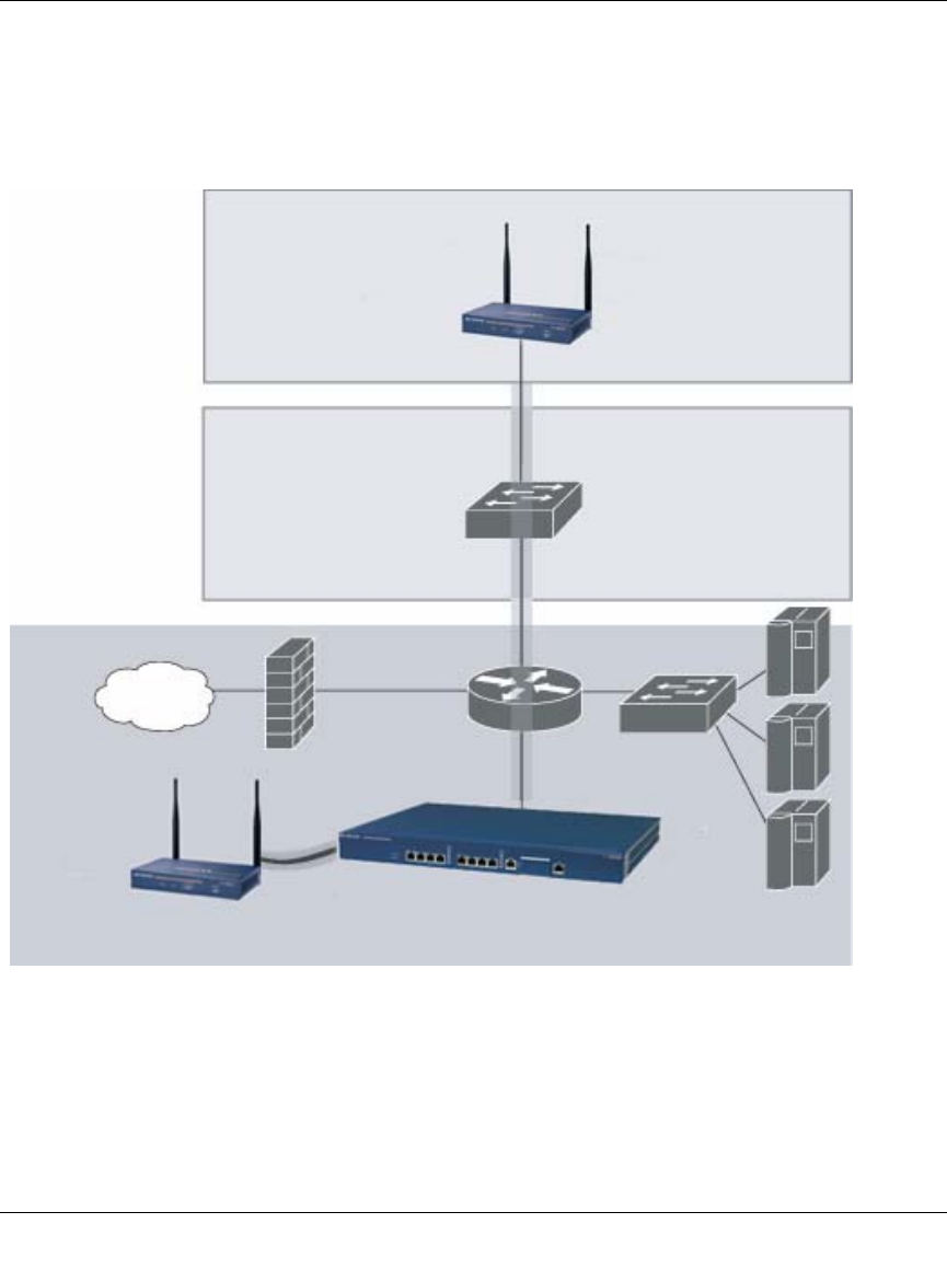
You can connect an AP to a WFS709TP either directly with an Ethernet cable or remotely through
an IP network. Figure 1-1 shows two APs connected to an WFS709TP. One AP is connected to a
switch in the wiring closet that is connected to a router in the data center where the WFS709TP is
located. The Ethernet port on the other AP is cabled directly to a port on the WFS709TP.
Access points used with the WFS709TP are Light APs, which means their primary function is to
receive and transmit wireless RF signals; other WLAN processing is left to the WFS709TP itself.
When powered on, an AP locates its host switch through a variety of methods, including the Aruba
Discovery Protocol (ADP), Domain Name Service (DNS), or D ynamic Host Configuration
Figure 1-1
Netgear AP
connected
through an IP
network
Internet
Floor
Netgear AP connected
with an Ethernet cable
WFS709TP
Wiring
closet
Data center