
User's Manual


Table Of Contents
- WFS709TP ProSafe Smart Wireless Switch Software Administration Manual
- Contents
- About This Manual
- Chapter 1 Overview of the WFS709TP
- Chapter 2 Deploying a Basic WFS709TP System
- Chapter 3 Configuring Network Parameters
- Chapter 4 RF Plan
- Chapter 5 Configuring WLANS
- Chapter 6 Configuring AAA Servers
- Chapter 7 Configuring 802.1x Authentication
- Chapter 8 Configuring the Captive Portal
- Chapter 9 Configuring MAC-Based Authentication
- Chapter 10 Adding Local WFS709TPs
- Chapter 11 Configuring Redundancy
- Chapter 12 Configuring Wireless Intrusion Protection
- Chapter 13 Configuring Management Utilities
- Chapter 14 Configuring WFS709TP for Voice
- Appendix A Configuring DHCP with Vendor-Specific Options
- Appendix B Windows Client Example Configuration for 802.1x
- Appendix C Internal Captive Portal
- Appendix D Related Documents
- Index
2-1
v1.0, June 2007
Chapter 2
Deploying a Basic WFS709TP System
This chapter describes how to connect a WFS709TP ProSafe Smart Wireless Switch and access
points (APs) to your wired network.
It includes the following topics:
• “Configuration Overview” on page 2-1
• “Configuring the WFS709TP” on page 2-5
• “Deploying APs” on page 2-14
• “Additional Configuration” on page 2-20
Configuration Overview
This section describes the tasks you need to perform in connecting a WFS709TP and APs to your
wired network in three typical deployment scenarios.
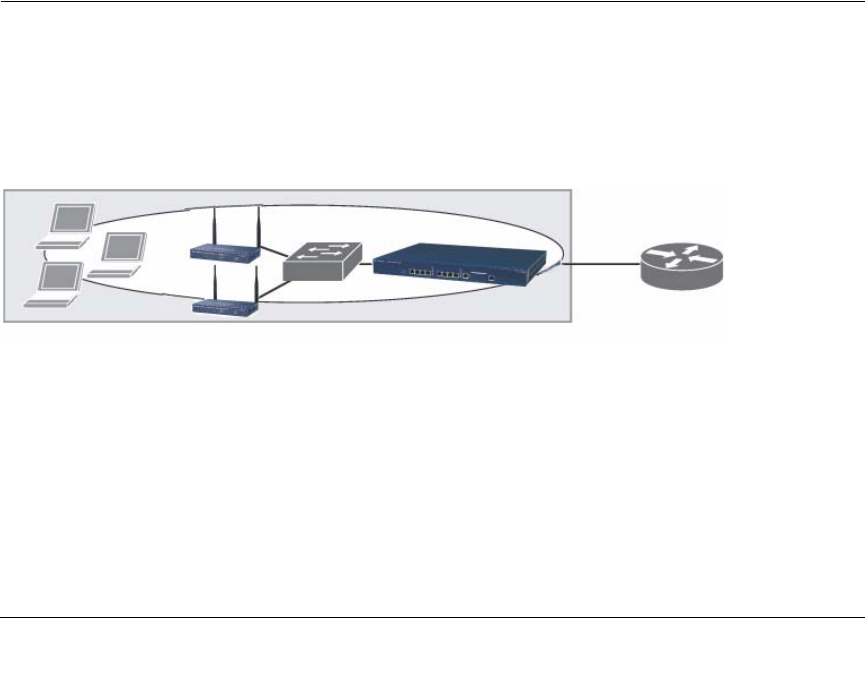
Deployment Scenario #1
In the deployment scenario shown in Figure 2-1, the APs and WFS709TP are on the same
subnetwork and will use IP addresses assigned to the subnetwork. There are no routers between
the APs and the WFS709TP; APs can be physically connected directly to the WFS709TP. The
uplink port on the WFS709TP is connected to a Layer 2 switch or router.
You need to perform the following tasks:
1. Run the initial setup (see“Run the Initial Setup” on page 2-6).
Figure 2-1
Router is
default
gateway for
WFS709TP
and clients