
User's Manual


Table Of Contents
- WFS709TP ProSafe Smart Wireless Switch Software Administration Manual
- Contents
- About This Manual
- Chapter 1 Overview of the WFS709TP
- Chapter 2 Deploying a Basic WFS709TP System
- Chapter 3 Configuring Network Parameters
- Chapter 4 RF Plan
- Chapter 5 Configuring WLANS
- Chapter 6 Configuring AAA Servers
- Chapter 7 Configuring 802.1x Authentication
- Chapter 8 Configuring the Captive Portal
- Chapter 9 Configuring MAC-Based Authentication
- Chapter 10 Adding Local WFS709TPs
- Chapter 11 Configuring Redundancy
- Chapter 12 Configuring Wireless Intrusion Protection
- Chapter 13 Configuring Management Utilities
- Chapter 14 Configuring WFS709TP for Voice
- Appendix A Configuring DHCP with Vendor-Specific Options
- Appendix B Windows Client Example Configuration for 802.1x
- Appendix C Internal Captive Portal
- Appendix D Related Documents
- Index
WFS709TP ProSafe Smart Wireless Switch Software Administration Manual
2-4 Deploying a Basic WFS709TP System
v1.0, June 2007
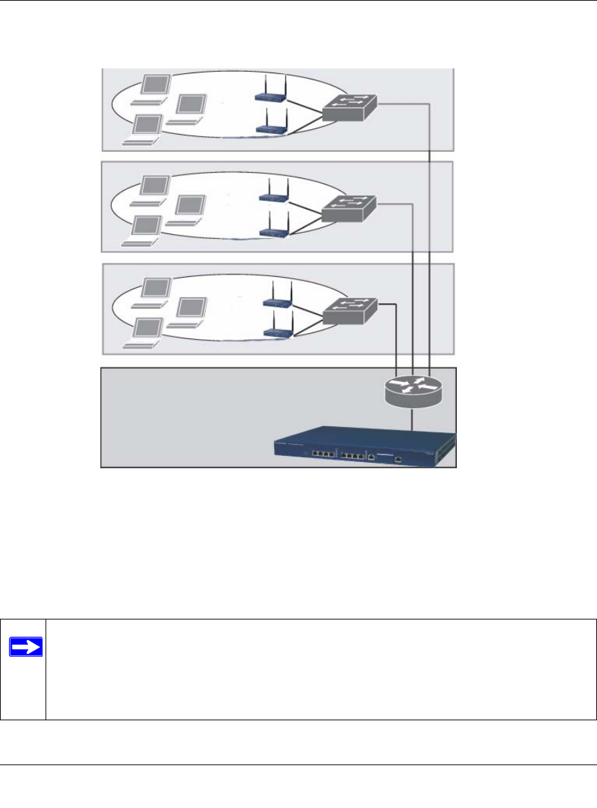
Deployment Scenario #3
In this deployment scenario (Figure 2-3), the APs and the WFS709TP are on different
subnetworks and the APs are on multiple subnetworks, with routers between the APs and the
WFS709TP. The WFS709TP is connected to a Layer 2 switch or router through a trunk port that
carries traffic for all wireless user VLANs. An upstream router functions as the default gateway for
the wireless users.
Figure 2-3
Note: This deployment scenario does not use VLAN 1 to connect to the Layer 2 switch or
router through the trunk port. When the initial setup prompts you for the IP address
and default gateway for VLAN 1, use the default values. In later steps, you will
configure the appropriate VLAN to connect to the switch or router as well as the
default gateway.
Floor 3
subnet
Floor 2
subnet
Floor 1
subnet
Data
center
Router is default
gateway for
WFS709TP and
clients
Trunk port
carries client
traffic