Start Here Congratulations on your purchase of the NETGEAR™ Model EN104, Model EN108, or Model EN116 Ethernet hub. The hubs deliver standards-based, plug-and-play networking solutions for small businesses, home offices, and low-density workgroups of larger companies. In this installation guide, all three hubs are referred to collectively as the Model EN104/EN108/ EN116 hub. Each hub is listed individually when information is provided that refers to a specific model.
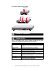
Verify that your package contains the following: • Model EN104 hub, Model EN108 hub, or Model EN116 hub • Mounting kit (for wall installation) • BNC T-connector and BNC 50 Ω terminator (only if you have purchased the Model EN108 hub or the Model EN116 hub) • This installation guide • Warranty & Owner Registration Card • Support Information Card • Power adapter and cord Product Illustration Front Panel of the Model EN104 hub 10BASE-T ports 10 BASE-T HUB Pwr (Power) Col (Collision) EN104 LINK
LEDs The table below describes the activity of the LEDs. Label Color Activity Description Pwr (Power) Green On Power is supplied to the hub. Col (Collision) Amber Blinking Data collision is occurring on the network. Note that occasional collisions are normal. Link (located on the top left corner of each vista 10BASE-T port) Green On The link between this port and the connected device is good.
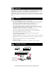
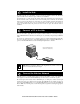
The rear panel also includes a DC power receptacle. BNC port LEDs BNC port Active BNC 12Vdc 1.2A Rx – + Rear Panel of the Model EN104 hub AUI port LEDs Power receptacle AUI port Active AUI Active Rx BNC 12Vdc 1.2A Rx – + Rear Panel of the Model EN108 hub Active AUI Rx Active BNC 12Vdc 1.2A Rx – + Rear Panel of the Model EN116 hub 8738FA Installation Procedures Prepare the Site Before you begin installing your hub, prepare the installation site.
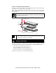
Install the Hub To install your hub on a flat surface, you do not need any special tools. Be sure the hub is positioned with at least 2 inches of space on all sides for ventilation. To install the hub on a wall, measure the distance between the mounting hole on the back of the hub and mark the wall to match the location of the mounting holes on the hub. At the marked location, screw into the wall the two screws that you received with the mounting kit included in your package contents.
Connecting Port on the Hub Connecting Device Cable Used Model EN104 hub: Ports 1–3 PC, server, or router Straight-through cable Ports 1–3 Hub or switch Crossover cable Ports 1–7 PC, server, or router Straight-through cable Ports 1–7 Hub or switch Crossover cable Ports 1–15 PC, server, or router Straight-through cable Ports 1–15 Hub or switch Crossover cable Model EN108 hub: Model EN116 hub: Set the Normal/Uplink Push Button If you are connecting to port 4 on the Model EN104 hub, port
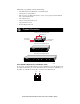
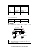
The following illustration shows cascading hubs together daisy-chain style and indicates the setting of the Normal/Uplink push button on each hub.
Connect to a Network Using the AUI Port The AUI port on the rear panel (found only on the Model EN108 hub and the Model EN116 hub) is normally used for connecting a thick coaxial segment. With the right type of transceiver, you can use the AUI port to connect to most types of network media, including 10BASE-T twisted pair cable or thin coaxial, thick coaxial, and 10BASE-FL fiber optic cables. Note: All transceivers connected to the AUI port must have the signal quality error (SQE) test function disabled.
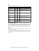
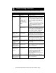
Troubleshooting Information Refer to this table and the information that follows the table to troubleshoot your hub. Symptom Cause Amber Col LED blinks. There is data collision on Data collision is normal on Ethernet networks. the network. No action is required. Amber Col LED blinks There is data collision on excessively. the network because the network is extremely busy or defective devices are connected on the network that cannot detect network traffic or collision.
Network Interface Cards Make sure the network interface cards installed in the workstations are in working condition and the software driver has been installed. Hub Integrity If required, verify the integrity of the hub by resetting it. Turn power to the switch off and then back on. If the problem continues and you have completed all the preceding diagnoses, contact NETGEAR Customer Support. For the phone number of the representative in your area, see “Customer Support.
RJ-45 Connector Pin Assignment Normal Assignment: Ports 1–3 on the Model EN104 hub Ports 1–7 on the Model EN108 hub Ports 1–15 on the Model EN116 hub Uplink Assignment: Port 4 on the Model EN104 hub Port 8 on the Model EN108 hub Port 16 on the Model EN116 hub 1 Input Receive Data + Output Transmit Data + 2 Input Receive Data - Output Transmit Data - 3 Output Transmit Data + Input Receive Data + 6 Output Transmit Data - Input Receive Data - 4, 5, 7, 8 Not used Not used AUI Connector The AUI
The BNC port on the hub, with the BNC T-connector and the 50 Ω terminator, is used for connecting to a thin coaxial segment. BNC T-connector 50 Ω terminator 50 OHM 8150FA Technical Specifications General Specifications Network Protocol and Standards Compatibility IEEE 802.3i, 10BASE-T, 10BASE-2, 10BASE-5 Ethernet 10 Mbps, Manchester encoded Data Rate 10BASE-T ports (RJ-45), BNC port, Interface AUI port (Model EN108 hub and Model EN116 hub only) Power Consumption Model EN104 hub 11.
© 1999 by NETGEAR, Inc. All rights reserved. Trademarks Bay Networks is a registered trademark of Bay Networks, Inc. NETGEAR is a trademark of Bay Networks, Inc. All other trademarks and registered trademarks are the property of their respective owners. Statement of Conditions In the interest of improving internal design, operational function, and/or reliability, NETGEAR reserves the right to make changes to the products described in this document without notice.
NETGEAR, Inc. A Bay Networks Company 4401 Great America Parkway Santa Clara, CA 95054 USA Phone: 888-NETGEAR http://WWW.NETGEARinc.