
User Guide


Table Of Contents
- WFS709TP ProSafe Smart Wireless Switch Software Administration Manual
- Contents
- About This Manual
- Chapter 1 Overview of the WFS709TP
- Chapter 2 Deploying a Basic WFS709TP System
- Chapter 3 Configuring Network Parameters
- Chapter 4 RF Plan
- Chapter 5 Configuring WLANS
- Chapter 6 Configuring AAA Servers
- Chapter 7 Configuring 802.1x Authentication
- Chapter 8 Configuring the Captive Portal
- Chapter 9 Configuring MAC-Based Authentication
- Chapter 10 Adding Local WFS709TPs
- Chapter 11 Configuring Redundancy
- Chapter 12 Configuring Wireless Intrusion Protection
- Chapter 13 Configuring Management Utilities
- Chapter 14 Configuring WFS709TP for Voice
- Appendix A Configuring DHCP with Vendor-Specific Options
- Appendix B Windows Client Example Configuration for 802.1x
- Appendix C Internal Captive Portal
- Appendix D Related Documents
- Index
WFS709TP ProSafe Smart Wireless Switch Software Administration Manual
RF Plan 4-7
v1.0, June 2007
When width and length are specified, RF Plan creates a rectangular area in the Planning
feature pages that represent the overall area covered by the building. You need to import an
appropriate background image (“Floor Editor Dialog Box” on page 4-12) to aid you in
defining areas that don’t require coverage or areas in which you do not wish to deploy APs and
AMs (“Area Editor Dialog Box” on page 4-13).
• Inter-Floor Height. This is the distance between floor surfaces in the building.
The valid range for this field is any integer from 1 to a value corresponding to 1x10
12
.
• Floors. Enter the number of floors in your building. The valid range for this field is any
integer from 1 to a value corresponding to 1x10
12
.
• Unit. Specify the unit of measurement for the dimensions you specified on the page. The
choices are feet and meters.
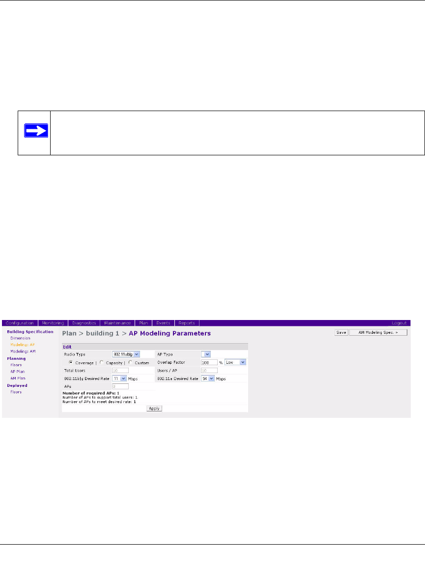
AP Modeling Parameters Page
The AP Modeling Parameters page (Figure 4-5) allows you to specify the information necessary
for RF Plan to determine the appropriate placement of your APs.
Controls on this page allow you to select or control the following functions, which are described in
further detail in this section:
• Radio Type. Use this pull-down menu to specify the radio type.
• AP Type. Use this drop-down box to select the AP model.
• Overlap Factor. Use this field and pull-down to specify an AP coverage overlap factor.
Note: The inter-floor height is not the distance from floor to ceiling. Some buildings
have a large space between the interior ceilings and the floor above.
Figure 4-5