
Manual


MAN-UTPLAMP REV0703A
NetMedia, Inc., 10940 N. Stallard Place, Tucson, Arizona 85737 (520) 544-4567 Fax: (520) 544-0800 Email: sales@netmedia.com www.netmedia.com
Frequently Asked Questions
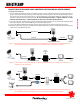
Q- Can I connect the camera to a computer network or another UTP video system?
A- NO! Do not connect the Camera/Decoder UTP cable to a computer network, or another UTP video system! Doing so
could damage this product and/or the other attached devices!
The Decoder ouputs DC voltage on pins 7 and 8 of its UTP
connector that the other equipment may not be prepared to handle. Each Camera/Decoder pair needs a dedicated
point-to-point circuit; nothing else can share its wires. Regarding computer networks, this is not an IP or Power over Ethernet
(PoE) device so it will not work properly with network hubs, switches, or routers. Regarding other UTP systems, the
Camera/Decoder video transmission signal is proprietary so no other device will be able to recognize or display it properly.
Q- How can I see the camera on my TV without using an expensive security monitor?
A- The composite video signal from the UTP Decoder can be plugged directly into one television’s RCA Video Input jack and
viewed when that TV is switched to the proper input. Another option is to feed the Decoder signal into a modulator. A
modulator, such as NetMedia’s MM70, changes the video to a UHF or Cable channel and allows the signal to be distributed to
all your TV’s along with the existing antenna/cable/satellite service.
Q- Is there some way I can use UTP cable for other types of cameras? What about their separate power wire requirement?
A- Yes, the NetMedia UTP Video Encoder and Decoder can be purchased as a set, NM-UTPSET, for use with other popular 12V DC
cameras. The Encoder will accept the camera’s composite video signal and provide about 150mA of regulated 12V DC power.
Q- Why do the light areas of the picture look washed out?
A- The camera’s automatic iris must decide how much to open for shadow areas or close for light areas. When a picture has both
light and shadow, the camera adjusts the iris based on the percentage of each area in the image. If it decides to open more for
the shadow portions then the light areas will be overexposed. In addition, cameras that are designed for low light or infrared
sensitivity typically favor the shadow areas and look more washed out under bright conditions. Try adjusting the image field
so that more light areas are visible and see if the iris closes to improve the picture. It is normal though, that as the lighting
conditions change throughout the day, so will the camera iris and the picture’s dark or light areas. With a long cable length,
adjusting the UTP Decoder DIP switches as described below may also improve the picture.
Q- Why are the shadow areas too dark to see much detail?
A- This is like the washed out question above except opposite. In this case, the camera’s automatic iris is opening more for the light
areas at the expense of the shadow areas. Try adjusting the image field so that more shadow areas are visible and see if the iris
opens to improve the picture. Keep in mind though, that the camera still does need some kind of light in order to see. If
necessary, add some lighting to the dark area to improve visibility. Again, with long cable lengths, adjusting the UTP Decoder
DIP switches as described below may improve the picture.
Q- Will the camera work at distances beyond 1000 feet?
A- Though we do not recommend or support doing so, some people find that the camera functions satisfactorily at distances
greater than 1000 feet. At that range, the video quality degrades as the cable length increases but until the power gives out
over the next few hundred feet, it may still be acceptable for your application.
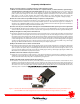
Q- What do the DIP switches inside the UTP Decoder module do?
A- The switches come preset from the factory in the OFF position. This requires the least amount of intervention for most
installations. Some monitoring devices though, are more sensitive to the voltage level of the video signal and will require an
adjustment of the switches according to the length of the UTP cable. In those situations, disconnect power from the Decoder
and remove one of the end plates. Then locate the switch bank and, starting from #1, set each switch ON until the most
satisfactory picture is attained. The longer the cable, the more switches that will need to be ON.
NM-UTPLAMP
satisfactory picture is attained. The longer the cable, the more switches that will need to be ON.
Figure 5 - UTP Decoder DIP Switches. Default of all OFF works for most installations. If necessary, start with #1 and
turn more ON as the cable length increases; turn them all ON for the longest distance, 1000 feet.