User Guide ® Netopia VOIP ATA User’s Guide User Guide 1-1
User Guide REVISION STATUS User Guide 1-2
User Guide Tables Of Content Chapter 1 - Introduction ............................................................................................... 1-6 1.1 Main features ............................................................................. 1-7 Chapter 2 - Your VOIP ATA at a glance ...................................................................... 2-8 2.1 Ports and buttons........................................................................ 2-8 2.2 LED description......................
User Guide 7.7 Address Book Configuration.................................................... 7-45 Chapter 8 – Admin Privilege ...................................................................................... 8-48 8.1 Miscellaneous Configuration.................................................... 8-48 8.2 Admin / Username Password Configuration............................. 8-49 8.3 Reset to Default ....................................................................... 8-51 8.
User Guide B1.2 Explanation of the Rules ........................................................ 10-66 B2 Calling Other Service Provider Numbers through Pulver........
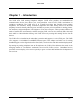
User Guide Chapter 1 - Introduction The VOIP ATA VoIP Analog Telephone Adaptor (VOIP ATA) products are standards-based communication devices that deliver true, next-generation voice-over-IP (VoIP) terminations to residences worldwide.
User Guide 1.1 Main features • Call Out & Call In • Voice over IP c all (through Gatekeeper) • IP address calling / Peer to Peer calling (Future Firmware Upgrade) • 3Way IP Conference call • • • • • • Call features Call Waiting Call Hold Call Forward: No Answer / Busy / All Call ID (Type 1 and 2) Call Transfer (Dependant on ITSP) • Setup & Configuration • Web Based Configuration • Password Protection for Web Configuration • • • • • • • Audio Codec Feature G.711, G.726, G.
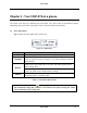
User Guide Chapter 2 - Your VOIP ATA at a glance The VOIP ATA may have different ports and LEDs. Let’s take a look at the different options. Depending upon your model, it may have some or all of the features listed below 2.1 Ports and buttons Fig 2-1 shows the back panel of the VOIP ATA. Figure 2-1 : Back Panel 12V DC MODEM RESET PHONE DESCRIPTIONS This is where you will connect the included power adapter.
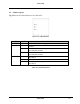
User Guide 2.2 LED description Fig 2-2 shows the LED indicators of the VOIP ATA. Figure 2-2 : LED Indicators LED PWR ETH STATUS On On Blinking Off PHONE On Blinking Off DESCRIPTIONS The VOIP ATA is receiving power. The VOIP ATA has an Ethernet connection with cable/DSL modem. The VOIP ATA is sending/receiving dVoIP ATA to/from the cable/DSL modem. The VOIP ATA doesn’t have an Ethernet connection with the cable/DSL modem. This port(s) is registered to the Internet Phone Service Provider(s).
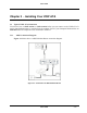
User Guide Chapter 3 - Installing Your VOIP ATA 3.1 Typical VOIP ATA Connection You need to have a ADSL modem or Cable modem before you can connect to the VOIP ATA. It can be placed behind router or straight from the modem. Check if your Computer/Notebook has an Ethernet Port. The Telephone set is connected to the RJ-11 3.1.1 ADSL Connection Diagram Figure 3-1 below shows a ADSL Modem+Router connection diagram.
User Guide 3.1.2 Cable Connection Diagram Figure 3-2 below shows a Cable Modem+Router connection diagram.
User Guide 3.2 For Company Network Connection Please seek advise from your company’s Network Administrator, to open UDP port 5060 for SIP Signaling and UDP ports 5000-5020 for RTP.
User Guide Chapter 4 - Setting Up Your VOIP ATA functionality via GUI 4.1 Access to VOIP ATA’s GUI To configure your VOIP ATA, you need to login to the device using a web browser. 4.1.1 Accessing GUI Using Static IP Figure 4.1: Accessing GUI Using Static IP These instructions are for the Windows 98, Windows ME, Windows 2000 and Windows XP operating systems. 1) In Windows XP, click Start-> Control Panel. In Windows 98/ME/2000, click Start-> Settings-> Control Panel.
User Guide 5) Select Use the following IP address and enter information as below: IP address : 192.168.1.XXX (IP Address set must be unique) Subnet mask : 255.255.255.
User Guide 6) Click OK to close the Internet Protocol (TCP/IP) Properties window. 7) Click Close (OK in Window 98/ME/2000) to close the Local Area Connection Properties window. 8) Close the Network Connections screen. 9) Launch your web browser and enter “192.168.1.200” at the address bar and hit Enter. 4.1.2 Accessing GUI Using Hub/Switch Figure 4.2: Accessing GUI Using Hub/Switch If your Router’s LAN is already in the192.168.1.XXX subnet, simply launch your web browser and enter “192.168.1.
User Guide 4) Launch your web browser and enter the assigned IP Address at the address bar and hit Enter.
User Guide 4.2 Setup Mode. 1) Upon successfully logging in, the Setup mode screen as shown in Figure 4.3 is displayed. 2) Click Step 1: Network Selection to start configurating the VOIP ATA. Figure 4.3 : Overall Status 3) Depending to your System Setup, select Connecting to a broadband router/cable modem and click Proceed to Step 2. Please refer to Figure 4.4.
User Guide Figure 4.4 : Network Selection 4) Fill in the fields with information exactly as it was given to you by your ITSP (Internet Telephony Service Provider) or network administrator. Please refer to Figure 4.5. Figure 4.5 : Step 2 5) Click Finish to save configuration and reboot the VOIP ATA. Please refer to Figure 4.6. 6) Click the Refresh button on your web browser after approximately 30-50 seconds. Figure 4.
User Guide Chapter 5 - Basic Mode 5.1 Overall Status It summarizes all the information regarding the WAN of the VOIP ATA. Figure: 5-2: Overall Status Firmware Version: This section displays the current version of VOIP ATA Firmware. Registration Status: This field displays the current registration status as defined in Table 5.1.
User Guide Current Voice Call Status: This field displays the current registration status as defined in Table 5.2.
User Guide 5.3 TCP Status This page displays all the relevant TCP packets and dVoIP ATA information. You can reset the counters to clear all the attributes. Figure: 5-4: TCP Status Reset Counters: This button allows user to reset the TCP Status counter. General: Total Packets, DVoIP ATA Packets, DVoIP ATA Bytes, Out of Order Packets, Out of Order Bytes Discarded Packets: Bad Checksum, Bad Offset Header, Too Short Connections: Initiated, Accepted, Established, Closed.
User Guide 5.4 System Log The System Log page shows the events triggered by the system. This page contains dynamic information and will refresh every 10 seconds. Figure: 5-5: System Log Clear Log: This field allows you to clear the current contents of the System Log. Save Log: This field allows you to save the current contents of the System Log by right clicking ‘here’ and select “Save Target As” to save it into a text file.
User Guide Chapter 6 - Basic Configurations 6.1 WAN Configuration This page let you configure the WAN settings. Figure 6-1 WAN Configuration Static IP Settings: IP Address: Range for IP Address is x.x.x.y, where 0 ≤ x≤ 255 and 1 ≤ y≤ 254, default is 192.168.241.101. Subnet Mask: Range for Subnet Mask is x.x.x.x, where 0 ≤ x≤ 255, default is 255.255.255.0 Gateway: Range for Gateway is x.x.x.y, where 0 ≤ x≤ 255 and 1 ≤ y≤ 254, default is 0.0.0.0.
User Guide 6.2 DNS Configuration The DNS Configuration page allows you to set the configuration of the DNS proxy. Figure 6-2 DNS Configuration DNS Proxy: When the DNS Proxy is Disabled, the LAN port does not process the DNS query message. For the DHCP requests from local PCs, the DHCP server will set the user-configured DNS server as the DNS server. Then all DNS query messages will be directly sent to the DNS servers. DNS Proxy is enabled by default.
User Guide This is the URL name for the DNS server. This can be up to 255 characters. Host IP: This is the IP address of the DNS Server. DNS Proxy Setting: This is a table of all DNS server IP addresses. DNS Server Setting: This is a table of all DNS sever URL names. Save Configuration: Clicking this will link the user to the Save Settings / Reboot page.
User Guide 6.3 Save Settings / Reboot You can save the custimized settings in this section Figure 6-3 Save Settings / Reboot Save & Reboot: Click this to apply all changes. Reboot Only: Do this to discard all changes since last save. After either one of these buttons are clicked, the ADSL Bridge/Router will do the following: • Save & Reboot: Two pages will appear after pressing this button. The first one states: “Your settings are being saved and the modem being rebooted.
User Guide Figure 6-5 Rebooting Modem User Guide 6-27
User Guide Chapter 7 – Advanced Mode It provides a brief outline of the advanced features of individual hyper links on the left menu. 7.1 VOIP ATA Configuration The VOIP ATA Configuration page allows you to set different parameters of the VoIP application. Figure 7-1 VOIP ATA Configuration PTM Software Version details: This section displays the current version of the PTM module. Service Provider To Use: This parameter holds the service provider selected to work with the VOIP ATA for the above chosen Line.
User Guide Note There will not be any Dial Tone when WAN interface is down or Registration is Failed.
User Guide 7.2 SIP Service Provider The VOIP ATA SIP Service Provider Configuration page allows the user to set the configuration related to the SIP service provider. Figure 7-2 VOIP ATA SIP Service Provider Configuration Service Provider List: • This selection is a drop-down box, which allows the user to select the Service Provider for which the configuration needs to be done. When a service provider is selected from this dynamic list, the respective parameters are automatically displayed.
User Guide This parameter is the IP address of the Outbound proxy server. This is useful in cases where the VOIP ATA is behind a NAT.
User Guide Authentication Method: This parameter indicates the authentication method. Currently, only MD5 is supported. • AUTH_NONE: Disable any authentication method • AUTH_MD5: Use MD5 authentication method. Registrar Port: This parameter informs the port of the registrar on which it will listen for Register requests from the VOIP ATA. (Default Port is 5060) Note Range for Registrar port address is between 5000 and 65535.
User Guide 7.3 VOIP ATA Login Account Configuration The VOIP ATA Login Account Configuration page allows the user to set and configure login accounts for the service provider chosen in the index webpage, i.e., for the currently selected service provider in the main webpage. Figure 7-3 VOIP ATA Login Account Configuration User Profile List: This selection is a drop-down box, which allows the user to select the login account for which the configuration needs to be done.
User Guide Login Action: The VOIP ATA provides a drop-down option (Display, Add, or Edit or Delete) for the user to manipulate the various login parameters for login account chosen in the Login Account List. Parameters for a login account can be displayed, added, and edited. • • • • Display: This is the default option; selection of this option will display the selected login details after clicking on the Submit button.
User Guide 7.4 VOIP ATA Timer Configuration The VOIP ATA Timer Configuration page provides a number of timers used at the system level, which can be configured through the web interface. The timer values have to be given in seconds only. This section explains the various timers available for configuration. Figure 7-4 VOIP ATA Timer Configuration Predial Timeout: Dial timer indicates the time period through which the dial tone is heard once the phone has been lifted off the hook.
User Guide CallWaiting Timer indicates the period for which the call-waiting tone will be played when an incoming call arrives in the connected state. The Call Waiting tone is played at an interval of 10 sec. It is configurable using the Call Waiting tone parameters.
User Guide Call Fwd No Ans Timeout: CallFwdNoAns Timer indicates the time after which the call will be forwarded when not answered by anyone. This timer is applicable when Call Forwarding on No Answer is enabled. Submit Changes: Clicking on this button will save settings to the board RAM.
User Guide 7.5 Ringtone Configuration The Country Specific Ring & Tones Configuration page is used to define the parameters for the various tones (ring, dial, busy, ring back etc.) that are generated by the VOIP ATA application. VOIP ATA provides default Ring-Tone Parameters configured for various Countries. Flexibility is provided to change the existing ring-tone parameters and add new countries and also edit/delete existing countries.
User Guide The Ring Parameters are defined by five fields: Frequency, OnTime1, OffTime1, OnTime2, and OffTime2. Time values are in milliseconds. Frequency is given in hertz.
User Guide Normal Dial Tone: The dial tone parameters are defined by six fields: Freq1, Freq2, OnTime1, OffTime1, OnTime2, and OffTime2. RingBack tone: The ring back tone parameters are defined by six fields: Freq1, Freq2, OnTime1, OffTime1, OnTime2, and OffTime2. Alerting Tone: The alerting tone parameters are defined by six fields: Freq1, Freq2, OnTime1, OffTime1, OnTime2, and OffTime2. Recall Tone: The recall tone parameters are defined by five fields: Freq1, Freq2, OnTime1, OffTime1 and Duration.
User Guide • • Edit: Selection of edit option will overwrite the selected country’s (according the Working Country field) parameters with the current parameters displayed on the web page. The New Country field is optional and needs to be filled only when the country name also has to be changed. Delete: Selection of the Delete option will delete the selected Working Country from the country list. Submit Changes: Clicking on this button will save settings to the board RAM.
User Guide 7.6 Misc Configuration The Misc Configuration pages configures system-level parameters. This has three sections: SIP Device, STUN Parameters and Codec Preference. Figure 7-6 VOIP ATA Misc Configuration SIP Device: This section configures the following infomartion: • Local SIP Port: Enter the local SIP Port number on which VOIP ATA should listen for the messages. The range is 1 to 65535. (Default port is 5060) • Media Base Port: Enter the Media Base Port (also known as RTP port) number.
User Guide Select ENABLED to enable STUN (default) if the VOIP ATA is behind a NAT enabled router and the router has no ALG for SIP, or DISABLED to disable STUN (VOIP ATA is not to use STUN for NAT traversal). VOIP ATA also supports a proprietary implementation of NAT traversal where the Service provider is expected to provide some relay support. If DISABLED is selected, then based on the responses received, the VOIP ATA will dynamically determine if the SIP Server supports the proprietary implementation.
User Guide Note Even when STUN is enabled, the VOIP ATA does an automatic detection of the presence of SIP ALG and disables the use of STUN. This is to avoid some media problems arising out of the behavior of some ALGs when STUN is used at the user end. STUN Server: Enter the IP address or Domain Name of the STUN Server. The default is 66.7.238.210. This field is applicable only if USE STUN is selected as the NAT traversal technique.
User Guide 7.7 Address Book Configuration The Address Book Configuration web page allows for configuration of address book entries which can be used for speed dial execution of calls. Figure 7-5 Address Book The top half of the web page displays the current address book table. The bottom half of the web page can be used for editing the address book.
User Guide Port Number: Specify the SIP port number on which the remote end will receive our call. This is useful when you want to specify a non-phone number entry, where the call can be made directly without going through the configured proxy server. When this field is not specified, the default SIP port of 5060 will be assumed.
User Guide Speed dial code: This refers to the index in the address book as well as the speed dial entry code. This needs to be specified following *78 to dial out the number corresponding to this address book entry. Address Book Action: Select a drop-down option (DISPLAY, ADD, EDIT, or DELETE) to manipulate the various address book parameters for the entry index selected from the speed dial code drop down box.
User Guide Chapter 8 – Admin Privilege 8.1 Miscellaneous Configuration This page allows you to configure the miscellaneous configurations such as HTTP, FTP, TFTP and SNTP. Figure 8-1 Miscellaneous Configurations HTTP Server: HTTP Server Access: This field allows you to configure where these Web pages can be accessed from. • All: When this field is checked, it allows both WAN access to the Web pages.
User Guide HTTP Password Protection: This field allows you to enable or disable the HTTP authentication. (Default is Disabled) FTP Server: This field allows you to enable or disable the FTP server connection. (Default is Enabled) • Disable WAN side FTP access: This will disable WAN side access to the FTP server. (Default is Disabled) TFTP Server: This field allows you to enable or disable the TFTP connection. System default is Disabled.
User Guide Note.. FTP uses the same Username and Password. Ensure to click Submit and Save Settings for your configuration to take effect.
User Guide 8.3 Reset to Default This page allows you to reset the VOIP ATA to original factory default configuration. Figure 8-3: Restore Settings Click on Restore button to restore to factory default settings. Note.. This feature produces the same effect as press the Reset Button for more than 5 seconds..
User Guide 8.4 Firmware Update This page allows the user to upgrade the firmware via web interface. Figure 8-4: Firmware Update 8.4.1 How to Firmware Update 1) Access Firmware Update GUI at Advanced Firmware Update. 2) On the Firmware Update GUI as in Figure 8-4, click Firmware Update and GUI as in Figure 8-5 will be displayed, showing that VOIP ATA is preparing itself to attempt Firmware Update.
User Guide Figure 8-6: Uploading .DLF file 3) Refering to Figure 8-6 , click Browse, search for the correct .DLF file and click Upload to begin Firmware Update. 4) Click Cancel Update if you want to abort Firmware Update. Warning! As the uploading process will take about 1minutes, please do not turn off the VOIP ATA. 5) Firmware Updating is successful if GUI as shown in Figure 8-7 is displayed. Figure 8-7: Firmware Update Successful 6) As by default the VOIP ATA is set to Static IP, please refer to 4.1.
User Guide 8.5 Save / Reboot This page allows you to save the new configurations to the flash and reboot the VOIP ATA or simply reboot the VOIP ATA without saving changes. Figure 8-13: Save / Reboot Save & Reboot: Click this to apply all changes. Reboot Only: Do this to discard all changes since last save. After either one of these buttons are clicked, the ADSL Bridge/Router will do the following: • Save & Reboot: Two pages will appear after pressing this button.
User Guide • Reboot Only: Two pages will appear after pressing this button. The first one states: “The VOIP ATA is being rebooted. Reboot in progress, please wait….” Followed by “The modem is being rebooted. Done.
User Guide Chapter 9 Making Phone Calls 9.1 Internet Calls 1) To make a VoIP call, simply dial the SIP number on your phone’s dial pad. 9.2 PSTN Calls 1) To call regular PSTN telephone numbers, please use your ITSP’s dialing plan. 9.3 VoIP Advanced Call Features 9.3.1 Consultation Hold This feature allows a user to put the existing call on hold and call another number. How To: 1) Dial *83 followed by # on A’s dial-pad to disable 3-Way Conferencing for the duration of the following call.
User Guide 9.3.3 Attended Transfer This feature allows a user (transferor) to transfer an existing call (transferee) to another telephone number after first consulting with the dialed party (transfer target) before the user hangs up. How To: 1) During an existing call, press the flash button on the telephone handset to put the existing party on hold and get a dial tone. 2) Dial the telephone number to which the existing party is being transferred.
User Guide 9.3.6 Call Forwarding The VOIP ATA can control call forwarding at the end-point level. There are three types of call forwarding: • Forward Unconditional—Forwards every call that comes in. • Forward When Busy—Forwards calls when the line is busy. • Forward on No Answer—Forwards calls when the telephone is not answered after the configured period.
User Guide 9.3.6.1 Forward Unconditional How To: 1) Press *72 on your telephone dial-pad. 2) You will hear an alert tone very briefly, following which you can enter the number you want to forward call to; then press # again. 3) If you enter a number, then the VOIP ATA will attempt to call the number to which you intend to forward. Once you disconnect the attempted call, in subsequent call attempts you will listen stutter dial tone indicating that Forward Unconditional is enabled. 9.3.6.
User Guide 9.3.6.4 Canceling Call Forwarding How To: To cancel unconditional call forwarding, press *73 on your telephone dial-pad. To cancel call forwarding on busy press *76 on your telephone dial-pad. To cancel call forwarding on no answer press *77 on your telephone dial-pad. 9.3.7 Call Return The VOIP ATA provides the facility to call back the last incoming call that may have been missed.
User Guide Chapter 10 - Troubleshooting PROBLEM None of the LEDs turn on CORRECTIVE ACTION Make sure that you have the correct power adaptor connected to the VOIP ATA and plug into an appropriate power source. Check all cable connections. Cannot access the Internet Verify the Internet connection settings in the Overall Status screen. There is no dial tone Check the telephone connections.
User Guide Appendix A Glossary The Glossary defines acronyms, keywords and definitions used in this user guide.
User Guide DHCP Dynamic Host Configuration Protocol: A communications protocol that allows network administrators to manage and assign IP addresses to computers within the network. DHCP provides a unique address to a computer in the network which enables it to connect to the Internet through Internet Protocol (IP). DHCP can lease and IP address or provide a permanent static address to those computers who need it (servers, etc.).
User Guide DNS Domain Name System: A method to locate and translate Domain Names into Internet Protocol (IP) addresses, where a Domain Name is a simple and meaningful name for an Internet address. FTP File Transfer Protocol: A standardized internet protocol which is the simplest way to transfer files from one computer to another over the internet. FTP uses the Internet's TCP/IP protocols to function. Gateway A point on the network, which is an entrance to another network.
User Guide UDP User DVoIP ATAgram Protocol: A protocol that is used instead of TCP when reliable delivery is not required. Unlike TCP, UDP does not require an acknowledgement (handshake) from the receiving end. UDP sends packets in one-way transmissions.
User Guide Appendix B Dial Plan for Pulver B1 Basic Dial Plan An example dial plan string as would be used with Pulver (a globally available Void service provider - http://www.fwd.pulver.com) is given below. The dial plan string represents only the basic dialing call and service rules. B1.1 Pulver - USA Dial Plan [1-9]x.2t8>#x.6t4|*18x.8t8xt2>#|**484x.7t4>#|1:*72;>#x.etfxt2|2:*73;>#t4|3:*74;>#x.etfxt2| 4:*75;>#x.etfxt2|11:*70;>#t4|12:*69;>#t4||16:*90;x>#x.dtfxt2|18:*47;t4xt2>#|20:#;x.3>#x.
User Guide User Guide 10-67
User Guide B2 Calling Other Service Provider Numbers through Pulver Pulver also provides the facility to call other service provider numbers. The following is an example list of those service providers and the corresponding recommended dial plan rules that need to be configured for each of them. Please check their website for the complete list of supported service providers: (http://www.fwd.pulver.com/content/view/full/333/) Service Provider Partner NIC.at Vonage CallUK..
User Guide © Copyright September 2005. All Rights Reserved.