
User Manual


SRU Installation
17286-1000 Rev. B 03/14/01
SRU Inst alla tion Manual
2-13
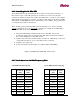
Figure 2-10 Wall Mount
Figure 2-11 Tripod Mount
When selecting a physical location, ensure that there is enough room to swing (pan) the
antenna during antenna alignment and that all the adjustable hardware is accessible.
The mounting location of the radio/antenna assembly on the pole mount as well as the
routing of the coaxial interface cable should be decided upon in advance.
All the mounts will accommodate a maximum pole diameter of 115mm [4.5 inches] with
the supplied V-clamp bolts. The minimum pole diameter is 60mm [2.4 inches].
2.4 .1.2
2.4 .1.22.4 .1.2
2.4 .1.2
Tools Required
Tools RequiredTools Required
Tools Required
The following tools will be required to install the radio/antenna mount:
•
17mm (0.7in) combination (open and box end) wrench.
•
Socket wrench, 3/8 inch (0.95cm) drive with 2-3 inch (5-7.6cm) extension and
17mm (0.7in) 6-point deep socket. An adjustable torque setting is recommended.
•
Ratchet wrench, 17mm (0.7in).
2.4 .1.3
2.4 .1.32.4 .1.3
2.4 .1.3
Inst allat ion Inst ruct ions and Specifica t ions
Inst allat ion Inst ruct ions and Specifica t ionsInst allat ion Inst ruct ions and Specifica t ions
Inst allat ion Inst ruct ions and Specifica t ions
Mechanical specifications for the antennae, including adjustment ranges, weights, wind
loading, and antenna mounts are included with the installation instructions shipped with
each unit.
2.4 .2
2.4 .22.4 .2
2.4 .2
Pre-inst allat ion Pre para t ion of t he Ant enna and Radio
Pre-inst allat ion Pre para t ion of t he Ant enna and RadioPre-inst allat ion Pre para t ion of t he Ant enna and Radio
Pre-inst allat ion Pre para t ion of t he Ant enna and Radio
Assemblies
AssembliesAssemblies
Assemblies
Prior to installation prepare the radio and antenna as follows:
1.
Record the serial number of the antenna for future reference.
2.
Determine the appropriate polarization for the radio and antenna. The radio unit
(SL) can be installed with horizontal or vertical polarization (see section 2.4.3
and Figure 2-12). If the radio will be horizontally polarized*, change the
polarization of the antenna using the instructions provided in section 2.4.3.1. If
the radio will be vertically polarized (which is the antenna default), proceed to
step 3.
*Note: Consult the Netro product catalog to determine availability of horizontal
polarization.
3.
Remove the protective cap from the antenna waveguide aperture.
4.
Remove the protective cap from the radio waveguide aperture.