
User Manual

SRU Installation
17286-1000 Rev. B 03/14/01
SRU Installation Manual
1-3
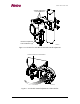
the SRU is drastically out of alignment. Re-align the SRU visually and wait for it to re-
admit. If the reading is between 0 Volts and 4 Volts, then the SAS has admitted.
Tighten the lock nut/washers to eliminate most freeplay, but not so tight that you can’t
move the SRU in both directions.
During the rough alignment procedure (see below) the purpose is to align the SRU visually,
both elevation and azimuth. If it is totally off-lobes it will read very high (and you’ll be able
to see that it is not aligned). Attach the voltmeter. Adjust it visually in both dimensions to
determine where the main lobe is centered.
Adjust the azimuth for the maximum reading. Tighten the azimuth bolts bit by bit without
losing the reading. Repeat for elevation. Remove the voltmeter and replace the hanging cap.
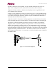
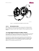
The purpose of the fine alignment procedure (see below) is to achieve precise antenna
alignment, which is critical for optimum system performance. Make sure the antenna is
aligned on the main lobe as shown in Figure 1-2, this arrangement produces a significantly
lower receive signal strength, making your system more vulnerable to outage due to fading.
Parabolic antennas are highly directional (focused) and any movement of the antenna during
alignment should be performed SLOWLY. This allows observation of the side and main
lobes during antenna movement. It is important to verify that the SRU antenna is aligned to
the MAIN LOBE.
Figure 1-2 Correct Antenna Alignment