
User Manual

SRU Installation
17286-1000 Rev. B 03/14/01
SRU Installation Manual
1-7
1.2.4
1.2.41.2.4
1.2.4
Final Alignment
Final AlignmentFinal Alignment
Final Alignment
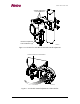
After completion of the initial alignment procedure, begin to further align the antenna. This
alignment is accomplished by adjusting the elevation and azimuth while observing the
Receive Signal Level (RSL).
This adjustment procedure involves panning the antennas in order to zero-in on the
maximum receive signal, as indicated on a voltmeter, thereby properly aligning the main
lobe of the microwave radiation pattern.
NOTE
Several alarms remain active until the installation has been completed. When the radio
link becomes functional, the red SRU Alarm LED extinguishes on the SAS front panel.
1.2.4.1
1.2.4.11.2.4.1
1.2.4.1
Panning
PanningPanning
Panning
SRU Antenna
SRU Antenna SRU Antenna
SRU Antenna
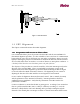
To maximize the RSL, connect the voltmeter to the RSL BNC connector on the SRU and
pan the antenna by moving the adjustments through the voltage peaks on the voltmeter.
Continue adjusting it in the same direction until the voltage decreases and then increases it
again. Use this method to identify the minor side lobes, which have lower peaks than the
major lobe. After identifying the side lobes, adjust back to the maximum voltage again.
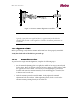
This procedure must be performed on both the elevation and the azimuth directions. This
method of panning the antenna ensures accurate alignment on the center of the main lobe.
1.2.5
1.2.51.2.5
1.2.5
RSL Calculation and Verification
RSL Calculation and VerificationRSL Calculation and Verification
RSL Calculation and Verification
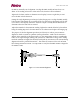
The measured RSL of properly aligned antennas with an unobstructed path should be
±
3 dB
of the calculated RSL for an ST at the center of the main beam. For an ST at a 3 dB point
of the main beam, the power will be 3 dB less. How you planned your network will
determine the beam width and 3 dB points of the BRU main beam and the direction of the
SRU relative to the BRU main beam center and 3 dB points
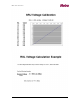
A professional microwave propagation path engineering program is recommended for
calculating the RSL. The Path Explorer program from Netro Corporation can perform
initial path calculations. The Path Explorer program can calculate the expected RSL in
either dBm, or the voltage related to the calibrated voltage at the BNC connector