Operating instructions for Netter Electric External Vibrators series NEA/NEG/NEG S/NES These operating instructions apply to: Series NEA Series NEG Series NEG S Series NES Sept. 2020 No.
Contents 1 General information 3 2 Safety 6 3 Technical data 11 4 Design and function 13 5 Transport and storage 14 6 Installation 15 7 Start-up and operation 19 8 Maintenance and servicing 26 9 Troubleshooting 31 10 Spare parts and accessories 33 11 Disposal 35 Scope of delivery Please refer to the delivery note for the scope of delivery. Check the packaging for possible transport damage.
General information 1 General information Use and storage Before installing the NEA/NEG read these instructions carefully. It is the basis for any action when dealing with the NEA/NEG, and may be used for training purposes. The instructions should be subsequently stored at the operation site. Target group The target group for these instructions is technical staff, who have basic knowledge of mechanics, electrics and explosion protection. Only complying technical staff may work on the NEA/NEG.
General information NEA/NEG from housing size 100 upwards are suitable for use in potentially explosive areas of the category 2D in the zone 21 and 22. In particular the standards DIN EN IEC 60079-0 and DIN EN 60079-31 (IEC 60079-31) are observed. Before using the NEA/NEG the operator must exclude the possibility that the introduction of vibrational energy poses the risk of explosion.
General information Notes IMPORTANT indicates actions, methods or notes that are not relative to safety, e.g. useful information and tips. Environmentally safe disposal indicates the obligation of environmentally safe disposal. Explosion prevention indicates information on explosion prevention. ATEX-notes When operating the NEA/NEG in potentially explosive areas all notes, marked with the Ex-symbol , must be observed.
Safety 2 Safety Intended use The NEA/NEG are intended for generating circular vibrations. General applications are: loosening, conveying, sorting, compacting, separating bulk materials and reducing friction. NEA/NEG are used for emptying bunkers, as drives for conveyor troughs, sieves and vibrating tables. The NEA/NEG are designed for installation in machines and may only be put into operation, if it has been assured that the complete machine complies with the regulations of the machinery directive.
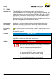
Safety High voltage DANGER Risk of electric shock due to high voltage An electric shock leads to serious injuries or even death. Observe the permissible protection class and earthing. The NEA/NEG may only be operated with the correct connection of the protective conductor. Perform all work only with insulated tools suitable for the application. All work on the system may only be carried out in a voltfree state. Never open the terminal box cover when voltage is applied.
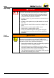
Safety Spark formation WARNING Spark formation The impact of corroded steel parts on the aluminium housing at high speed can cause spark formation and thus lead to an explosion. Choose the installation position carefully, so that there are no external impacts. Fasten the NEA/NEG securely. Check the fastening regularly (generally monthly). Static electricity WARNING Hazard of electrostatic discharge When cleaning the NEA/NEG with a dry cloth there is a risk of electrostatic discharge.
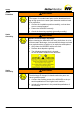
Safety Hot surface WARNING Hot surface If the permissible operating conditions and the maintenance requirements are not observed or if the vibrator does not fit the application, the housing surface may become very hot. In Ex-zones there is a risk of ignition of an explosive atmosphere due to hot surfaces. Observe all permissible operating conditions. Carry out the specified maintenance work at the predefined intervals.
Safety Falling parts WARNING Falling parts The NEA/NEG or parts of the construction can come loose due to vibration. Falling parts can lead to severe personal injuries. Use only suitable fastening screws and safety washer to attach the NEA/NEG. For attachment NetterVibration recommends using Netter fastening kits NBS. Check the fastening screws after one hour of operation and thereafter regularly (generally monthly). Retighten the fastening screws, if necessary.
Technical data 3 Technical data Permissible operating conditions Nominal voltage, nominal frequency The main voltage and the main frequency must comply with the nominal voltage and nominal frequency indicated on the type plate. Permissible Voltage deviation: +/- 5 % Permissible frequency deviation: +/- 2 % Possible power supply with: fixed voltage and frequency or frequency converter The operation of NEG with frequency converters allows rotary speeds > nominal frequency.
Technical data 1 2 3 4 5 6 7 Type plate for housing sizes 50 and 60 type designation rotary speed nominal voltage current phases serial number year of manufacture / degree of protection insulation class power nominal frequency centrifugal force duty cycle 8 9 10 11 12 13 ATEX certification 1 2 3 4 5 6 7 8 9 Type plate from housing size 100 type designation nominal voltage current phases / capacity power factor year of manufacture serial number max.
Design and function 4 Design and function Design Function Example: NEG 501140 Example: NEG 50120 Nr. Element Function 1 Housing Contains and protects the components of the NEA/NEG. 2 Unbalance covers Protect against grabbing into the unbalances. 3 Housing foot Attach the NEA/NEG to the mounting surface. 4 Type plate Shows model specific information and data. 5 Terminal box Housing sizes 101 to 120: terminal box integrated in housing foot. Contains the electrical connections.
Transport and storage 5 Transport and storage Observe the safety instructions in Ch. Safety, from page 6 on. Please refer to the brochure for weights and dimensions. Transportconditions When transporting the NEA/NEG, ensure that the NEA/NEG is not subjected to strong impacts or vibrations that could damage the bearings. Please observe the following notes: Use only the transport eyelet/eyelets (1) for lifting the NEA/NEG.
Installation 6 Installation Observe the safety instructions in Ch. Safety, from page 6 on. Please refer to the brochure for weights and dimensions. Fastening the NEA/NEG Important: For NEA/NEG with housing size 101 to 120 the terminal box is integrated in the housing foot. These vibrators must be electrically connected before fastening. The NEA/NEG can be operated in any position. 1.
Installation Electrical connection The following requirements and conditions must be met to connect the NEA/NEG electrically: The permissible operating conditions must be met. Please refer to chap. Technical data, page 11 for operating conditions. A suitable overload protection (1) must be pre-connected to each vibrator.
Installation Connection examples NEG The electrical parameters U, I, P on the type plate must be observed. Tighten terminal plate nuts with prescribed torque, see chap. Technical data, from page 11. Remember to put the safety washer between the ring and the nut and the vibration-damping insert back. The wire ends must be fitted with suitable insulated cable lugs, in order to prevent the strands from splaying.
Installation Connection diagram Series NEG / 3-phase current Connection examples NEA Smaller voltage Higher voltage 1: Earthing terminal for protective conductor 2: PTC-Thermistor connection (depending on the type) 1: Earthing terminal for protective conductor 2: PTC-Thermistor connection (depending on the type) Connect the NEA according to the type plate: 1 L1 N PE Cable with capacitor box 18 capacitor box outer conductor (brown) neutral conductor (blue) protective conductor (green-yellow) Capa
Start-up and operation 7 Start-up and operation Observe the safety instructions in Ch. Safety, from page 6 on. Permissible operating conditions Please refer to Ch. Technical data, page 11 for permissible operating conditions. Regulations When commissioning the NEA/NEG, the rules and regulations of the local associations for electrical engineering (e.g. VDE) and the valid accident prevention regulations must be observed.
Start-up and operation 3. 4. 5. 6. 7. Check that the cables are undamaged and laid according to the known regulations and standards. Check that all permissible operating conditions have been observed. Check that all protective measures on the system have been observed. Eliminate possible errors before start-up. Screw connections must be checked and, if necessary, retightened after 1 h operating time (after initial start-up) and thereafter regularly (generally monthly).
Start-up and operation Procedure: 1. 2. 3. 4. 5. 6. Number of unbalances Switch off the NEA/NEG at the main switch, secure against unintentional starting and ensure that there is no voltage. Loosen both unbalance covers. Loosen the locking nuts or locking screws. Bring the unbalances to the desired setting according to the following descriptions for the various unbalance discs. Note the mirrorsymmetrical setting. Retighten the locking nuts or locking screws.
Start-up and operation Type: NEG 22 Unbalance Type Type: Quantity NEG 50 Hz 60 Hz Unbalances Type Quantity 50 Hz 60 Hz 2530 XLs 6 6 162110 XS 4 4 2570 XLs 16 10 162550 XS 4 4 25210 XS 4 4 163030 XS 4 4 25420 XS 4 4 163820 XS 4 4 25540 XS 4 4 164700 XS 4 4 25700 XS 4 4 165190 XS 4 4 25930 XS 4 4 166270 XS 4 4 251410 XS 4 4 166670 XS 4 4 251800 XS 4 4 167890 XS 4 4 252060 XS 4 4 168500 XS 4 4 252370 XS 4 4 169510 X
Start-up and operation Unbalance discs type XL The centrifugal force is adjustable with the unbalance discs (lamella) of type XL in the following steps: 1: Number of unbalance discs per side 2: Default number of unbalance discs per vibrator 3: Centrifugal force in % There are 2 possibilities to adjust the unbalances: 1. 2. The unbalance adjustment (fine adjustment) is carried out by removing one unbalance disc on each side. All centrifugal values in % can be adjusted as specified in the table.
Start-up and operation Unbalances type XLs Settings The centrifugal force is adjustable with the unbalance discs (lamella) type XLs. Adjustment of the unbalances is carried out according to a scale disc or the supplementary sheet in the terminal box of the NEA/NEG. By rotating the outer, adjustable unbalance disc(s) to another position, the percentage of the centrifugal force changes as shown in the illustration below. The grid position is defined by position pins.
Start-up and operation Example: NEG 50120 / 50 Hz has a total of 6 unbalance discs (3 discs per side: 2 fixed, 1 adjustable). If a centrifugal force of 88% is desired, the adjustable unbalance discs are rotated anticlockwise on both sides into the fourth grid position. centrifugal force 100 % Unbalances type XS centrifugal force 88 % The unbalance setting of the unbalance discs of the type XS is carried out on the scale on the fixed unbalance.
Maintenance and servicing 8 Maintenance and servicing Observe the safety instructions in Ch. Safety, from page 6 on. Technical data Information regarding tightening torques for screws and nuts can be found in Ch. Technical data, page 11. Expertise and regulations Maintenance and servicing of the vibrators may only be performed by regularly trained, authorised and qualified personnel. Work on the electrical system may only be carried out by a qualified electrician.
Maintenance and servicing Interval Action Monthly Check screw connections and retighten if necessary. Check ball or roller bearings and relubricate if necessary, see section "lubrication". Damaged bearings or bearings whose service life has been reached, must be replaced immediately. Check cable supply line. Every 6 month Check proper condition of connecting cables and plugs. Every 2 years Replace O-rings and plastic seals .
Maintenance and servicing Lubrication / bearing life NEG Type of lubrication or grease quantity of the bearings and bearing life of the NEG: Type NEG Lubrication/ grease quantity [g] Bearing life [h] 50 Hz Bearing life [h] 60 Hz 5020 PL* 92,118 22,745 254310 40 8,200 7,300 5050 PL* 8,087 2,236 254900 80 9,930 8,648 5060 PL* > 100,000 5,044 256460 120 10,478 8,451 50120 PL* 18,075 18,075 258040 150 9,029 7,575 50200 PL* 3,363 2,572 258260 180 11,460 7,881 50300
Maintenance and servicing Type NEG Lubrication/ grease quantity [g] Bearing life [h] 50 Hz Bearing life [h] 60 Hz Type NEG Lubrication/ grease quantity [g] Bearing life [h] 50 Hz Bearing life [h] 60 Hz 12100 PL* > 100,000 > 100,000 122920 100 > 100,000 43,076 12180 PL* > 100,000 > 100,000 123530 120 > 100,000 35,405 12230 9 > 100,000 > 100,000 124440 150 > 100,000 32,368 12460 PL* > 100,000 > 100,000 127640 180 29,652 10,982 12640 PL* > 100,000 > 100,000 128520 2
Maintenance and servicing 1. 2. 3. Disassemble unbalances type XS: After removing the circlip (20) and loosening the clamping screws (16), the unbalances can be removed. Disassemble unbalances type XL and type XLs: Screw a long screw with the same thread into a tapped hole for the fastening screws (24) of the unbalance cover. Put a lever between the unbalance discs and this long screw. After loosening the locking nut (21), the unbalances can be removed from the shaft. 4.
Troubleshooting 9 Troubleshooting Observe the safety instructions in Ch. Safety, from page 6 on. Expertise and regulations Troubleshooting of the vibrators may only be performed by regularly trained, authorised and qualified personnel. Work on the electrical system may only be carried out by a qualified electrician. The qualified personnel has to work exclusively with tools suitable for the application. In the case of unauthorised intervention in the NEA/NEG there is no longer any warranty claim.
Troubleshooting Fault Possible cause Troubleshooting Excessive heating of the vibrator Wiring wrong / overload Check circuit diagram Mains voltage too low Check mains voltage and cable cross-section Too much grease in bearings Fill in correct ammount of grease No grease or not enough grease in bearings Fill in correct ammount of grease Foreign body in bearings Clean bearings, replace if necessary Phase interruption Check fuse, mains voltage and connection cable Short-circuit between turns in
Spare parts and accessories 10 Spare parts and accessories Ordering of spare parts Please provide the following details when ordering spare parts: type designation according to the type plate serial number according to the type plate description and position number of spare part required amount Example NEG 50300 Example NEG 501140 33
Spare parts and accessories Accessories The following accessories are available for NEA/NEG: Component Description Shim washers Compensation for removed unbalance discs. CC-unbalances Depending on the direction of rotation, two different unbalances can be achieved. Fastening kit NBS Recommended for secure and permanent fastening of the NEA/NEG. Frequency converters For frequency-controlled operation. Brake accessories Enable rapid deceleration of vibrators.
Disposal 11 Disposal Prices Materialspecifications All parts of the NEA/NEG must be properly disposed of according to the material specifications. The valid disposal prices of the NEA/NEG are available on request. All parts of the NEA/NEG can be recycled.