NTI R 1275 Danner Dr Tel:330-562-7070 NETWORK TECHNOLOGIES Aurora, OH 44202 Fax:330-562-1999 INCORPORATED www.nti1.
Table of Contents Introduction........................................................................................................... 1 Glossary ............................................................................................................... 1 Limitations ............................................................................................................ 1 Application Examples ........................................................................................... 2 Materials .
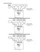
Application Examples 2
Materials Materials Supplied with this kit: • • • NTI ETH-4X1 / ETH-2X1 Manual Ethernet Switch 120VAC or 240VAC -12VDC/.5A AC Adapter This owner's manual Materials Not Supplied, BUT REQUIRED: • Ethernet Cables- Cat5(e)UTP straight-through with male-male connectors Preparation for Installation • A location should be chosen for the ETH-4X1 such that the ethernet cable from each supported device will reach it.
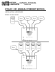
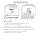
Features and Functions 1. Power- LED to indicate the ETH-4X1 Manual Ethernet Switch has power to operate 2. 12VDC .5A- female connection jack for the AC adapter 3. Select Switches- (1-4)- for manual control of "COMMON" and user selectable ports (1-4) 4. RS232- 9 pin DIN male (optional)- for computer control of "COMMON" and user selectable ports (1-4) 5. Status LEDs- for visual indication of switch connection between the "COMMON" and the user selectable ports (1-4) 6.
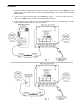
Installation 1. Position the ETH-4X1 Manual Ethernet Switch such that the ethernet cable from the COMMON , the AC adapter power cable, and the ethernet cables from the SELECTABLEs can reach the ETH-4X1 Manual Ethernet Switch. 2. Connect one end of an ethernet cable to the COMMON (See Fig.1.) Connect the other end of that cable to the "COMMON" port on the ETH-4X1 Manual Ethernet Switch. 3.
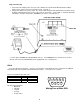
Plug-in and Boot Up 1. Connect the AC adapter power connector to the 12VDC port on the ETH-4X1 Manual Ethernet Switch. Make sure the power connector is properly inserted. (See Fig. 3.) 2. Plug the AC adapter into a power outlet. The “Power” LED on the ETH-4X1 Manual Ethernet Switch should illuminate indicating that a proper power connection has been made. Status LED "1" should also illuminate indicating a connection between the "COMMON" port and user selectable port 1. Fig. 3 3.
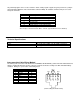
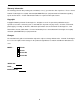
Any terminal program can be used to control the switch, if that program supports the given parameters (example HyperTerminal in Windows, Norton Commander terminal in DOS). An available standard serial port is needed. Accepted commands: Keystroke Action 1 Switch to port 1 2 Switch to port 2 3 Switch to port 3 (ETH-4x1-RS only) 4 Switch to port 4 (ETH-4x1-RS only) 0 Disconnect all D Deactivate buttons B Activate buttons (power-ON defaults) All other characters will be ignored.
Troubleshooting Each and every piece of every product produced by Network Technologies Inc is 100% tested to exacting specifications. We make every effort to insure trouble-free installation and operation of our products. If problems are encountered while installing this product, please look over the troubleshooting chart below. If an answer is not found in the chart, check the FAQs (Frequently Asked Questions) at our website at http://www.nti1.
Warranty Information The warranty period on this product (parts and labor) is one (1) year from the date of purchase. Please contact Network Technologies Inc at (800) 742-8324 (800-RGB-TECH) or (330) 562-7070 for information regarding repairs and/or returns. A return authorization number is required for all repairs/returns. Copyright Copyright © 2002 by Network Technologies Inc, all rights reserved.