NTI R 1275 Danner Dr Tel:330-562-7070 NETWORK TECHNOLOGIES Aurora, OH 44202 Fax:330-562-1999 www.networktechinc.
Warranty Information The warranty period on this product (parts and labor) is two (2) years from the date of purchase. Please contact Network Technologies Inc at (800) 742-8324 (800-RGB-TECH) or (330) 562-7070 or visit our website at http://www.networktechinc.com for information regarding repairs and/or returns. A return authorization number is required for all repairs/returns. COPYRIGHT Copyright © 1999-2007 by Network Technologies Inc. All rights reserved.
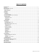
TABLE OF CONTENTS INTRODUCTION............................................................................................................................................................. 1 MATERIALS .................................................................................................................................................................... 1 FEATURES AND FUNCTIONS...........................................................................................................................
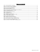
TABLE OF FIGURES Figure 1- Keyboard dip-switch configuration...................................................................................................................................... 3 Figure 2- Connect the monitor to the KEEMUX ................................................................................................................................. 3 Figure 3- Connect the user keyboard and mouse..............................................................................................
NTI KEEMUX Series PS/2 KVM Switch INTRODUCTION The KEEMUX PS/2 KVM switch (KEEMUX) enables access to several IBM PC-AT, PC-AT Clone or PS/2 CPUs from one monitor, keyboard and PS/2 mouse (up to 32 CPUs as a single switch or 152 CPUs when switches are cascaded). These CPUs can be file servers, network managers, etc. Internal microprocessor driven circuitry allows all CPUs to be booted simultaneously and error free with only one keyboard and mouse present.
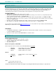
NTI KEEMUX Series PS/2 KVM Switch FEATURES AND FUNCTIONS Front View of KEEMUX-P8 3 NTI 2 1 R Network Technologies Inc Scan 2 1 3 4 5 6 7 Broad Com cast mand 1 8 8 On 5 4 1. Power ON/OFF switch 2. Mode LEDs- for visual indication of switch mode status 3. CPU Status LEDs- for visual indication of connection between the user and a specific CPU. 4. CPU Select Switches- push to manually switch to a specific CPU 5. Dip-switches- for configuring cascaded switches 6.
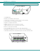
NTI KEEMUX Series PS/2 KVM Switch INSTALLATION Prepare To Connect 1. Before connecting the KEEMUX to the CPUs, make sure all CPUs, the monitor, and the KEEMUX are turned OFF. ! 2. WARNING! DAMAGE MAY OCCUR TO THE CPU IF POWER IS NOT DISCONNECTED BEFORE CONNECTING OR DISCONNECTING CABLES. The dip-switches on the front panel are configurable for several tasks. Switches 1-6 are used for cascading actions (see CASCADING on page 5) and switches 7 and 8 are for keyboard configuration.
NTI KEEMUX Series PS/2 KVM Switch 2. Connect the keyboard cable to the 6 pin miniDIN female port labeled “KEYBOARD” on the rear panel of the switch. Connect the mouse cable to the 6 pin miniDIN female port labeled “MOUSE” on the rear panel of the KEEMUX.
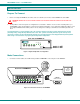
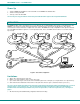
NTI KEEMUX Series PS/2 KVM Switch Power Up 1. 2. 3. Turn the KEEMUX power ON first. The mode LEDs on the KEEMUX should flash twice. Turn the monitor power ON. Turn any or all of the CPUs ON. FYI: Do not press any port buttons on the front panel until the PORT 1 light on the front panel illuminates. CASCADING The KEEMUX switch can be expanded to access up to 152 CPUs by cascading multiple units together, as illustrated below.
NTI KEEMUX Series PS/2 KVM Switch Configuration All 4, 8, and 16-port units are configured using the 8-position dip-switch (located on the front of each unit) according to tables 1 and 2 below.
NTI KEEMUX Series PS/2 KVM Switch 2. Connect Local CPUs to any remaining consecutive ports on the master as described under INSTALLATION on page 3. 3. Connect the RMT extension cables: a. With an RMT extension cable (REXT-SR-xx), connect the master’s “DAISY OUT” port to slave #1’s “DAISY IN” port. b. With another RMT extension cable, connect slave #1’s “DAISY OUT” port to slave #2’s “DAISY IN” port. (See Fig. 8 below.) c. Apply additional RMT extension cables until all slave units are connected together.
NTI KEEMUX Series PS/2 KVM Switch Keyboard Control Keyboard control of the KEEMUX can be achieved using either of two methods: • Basic Command Mode- operated strictly by using keyboard commands as instructed below. Basic Command Mode is only applicable if the OSD option is not built into the switch. • OSD Command Mode (optional)- operated using the keyboard and mouse in conjunction with On Screen Display (OSD) menus superimposed onto the monitor. If OSD is built in, use the menus as instructed on page 12.
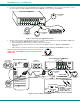
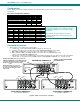
NTI KEEMUX Series PS/2 KVM Switch Port assignments ( KEEMUX-P4 ) PORT 3 PORT 4 - PORT 1 PORT 2 V I D E O V I D E O V I D E O V I D E O 4 3 2 1 C P U 4 5VDC 2A + CPU 4 C P U 3 CPU 3 C P U 1 C P U 2 CPU 2 CPU 1 NTI M O N I T O R R 1275 Danner Dr Aurora, OH 44202 www.nti1.com Tel:330-562-7070 Fax:330-562-1999 Mouse Keyboard Daisy Out Daisy In PS/2 DEVICES Figure 8- Connections grouped by port number Please note: If the switches are being cascaded (such as that illustrated in Fig.
NTI KEEMUX Series PS/2 KVM Switch OSD CONTROL (Optional) OSD superimposes a menu system on the user’s video screen with a list of all connected CPUs. OSD allows CPUs to be named (with up to 12-character names). OSD then allows selection of CPUs by that name. Connected CPUs can be listed by name or by port number. OSD Search Mode enables the user to type in the first few characters of the CPU's name and the OSD will locate it. Help screens assist with all OSD functions.
NTI KEEMUX Series PS/2 KVM Switch User Login Mode (Cont'd) Function: Submit user name/password Exit User Login Mode and return to previous mode. This function is only available if security is not currently active. Keystroke: Enter If the password submitted is incorrect, the user will not be able to proceed. If the password submitted is correct, the user will proceed to the maintenance menu for additional feature options. Esc .
NTI KEEMUX Series PS/2 KVM Switch System Access List The System Access List displays a list of numbers representing the ports so the administrator can change access rights to the ports for the selected user. The user’s name is displayed at the top of the access list. The mouse is used to change access rights by clicking on a given number to toggle a port’s status. A user that has access to a port can connect to that port and control the CPU connected to that port when in Normal Mode.
NTI KEEMUX Series PS/2 KVM Switch OSD Command Mode (Cont'd) Function: Keystroke: Sets scan time-out on each port Ctrl Selects a specific port Ctrl Enters Search Mode and adds a character to search string and selects the CPU’s name that matches best. A-Z 0-9 + T - + P - (0-2) x (0-9) x - (0-9) x - (0-9) x - (0-9) x (xxx from 002 to 255. ie. t002 would set the time-out period for 2 seconds) (Pxx would be P01, P02, etc.
NTI KEEMUX Series PS/2 KVM Switch Broadcast Mode (Use with extreme caution or commands intended for one CPU will be sent to all CPUs) Broadcast Mode allows the operator to send keystrokes to all active CPUs simultaneously (even those CPUs the user cannot connect to due to lack of security access ). To enter Broadcast Mode press + from Command Mode. Broadcast Mode is indicated by the illumination of the BROADCAST LED on the front panel. The BROADCAST LED will remain ON while in Broadcast Mode.
NTI KEEMUX Series PS/2 KVM Switch Search Mode Search Mode allows the user to enter and maneuver through a list of CPU names. As the user types, the best matching CPU name is selected. The list of CPUs may also be searched for a specific (or similar) name. From Command Mode, type any alphabetical or numeric character to enter Search Mode. The following commands are valid when the search option has been invoked from Command Mode.
NTI KEEMUX Series PS/2 KVM Switch Maintenance Mode (Cont’d) Function: Keystroke: Make OSD window taller T Make OSD window shorter S Change user password. (Present only when a standard user is logged in.) P Log current user out and return to User Login Mode. Q Activate security features. Present only when security is available but not active. A Enter Administration Mode. Option present only when administrator is logged in.
NTI KEEMUX Series PS/2 KVM Switch RS232 CONTROL (Optional) Rear View of KEEMUX-P4-RS - 5VDC 2A + NTI C P U 4 R 1275 Danner Dr Aurora, OH 44202 www.nti1.
NTI KEEMUX Series PS/2 KVM Switch Unit Address and Loop Back To allow multiple units to be controlled from a single CPU port, the RS232 control interface is designed to allow "daisy chaining" up to 15 units. By setting the appropriate RS232 dip switches, each unit can be given a unique address (1-15). Then the unit will only respond to commands on the bus if its address is embedded in the command. Use the table below to set the unit address.
NTI KEEMUX Series PS/2 KVM Switch Command Protocol Host controller commands supported by the unit are defined below. Notes: • All commands should be terminated with an (ASCII 13) denoted by . When a command is sent, the entire string is echoed back to the CPU along with a response from the addressed unit as shown in the command definitions. Unit response will be sent within 500 msec after . • Use a program that will send an entire command line all at once, not character by character.
NTI KEEMUX Series PS/2 KVM Switch RO - read single USER channel FORMAT: RO AA,XX RO = "read output" command followed by at least one space AA = unit address XX = output/USER to read RESPONSE: * (command received and executed OK) XX (XX = input/CPU connected) -OR? (syntax or transmission error occurred) RU - read unit size FORMAT: RU AA RU = "read unit size" command followed by at least one space AA = unit address RESPONSE: * (command received and executed OK) XX,YY (XX = #
NTI KEEMUX Series PS/2 KVM Switch HOW TO DISABLE OPERATING MODES The operating modes of the KEEMUX can be disabled if a user desires to do so. The Command Mode can be disabled which would also disable the Scan and Broadcast Modes, or, the Scan and/or Broadcast Modes can be individually disabled leaving the other features in Command Mode enabled. To disable these operating modes, the user must get access to the jumper block.
NTI KEEMUX Series PS/2 KVM Switch NOTE: Before proceeding, it is important to discharge any static charge you may be carrying by touching any large metal object (away from the KEEMUX). 4. The first visible circuit board, the uppermost board, is the video board. Along the back of the video board are between 3 and 5 video ribbons (depending on how many monitors the unit is designed to connect to) connecting the video board to a circuit board on the rear panel with 15HD connectors on it.
NTI KEEMUX Series PS/2 KVM Switch Configuring The Jumper Block Once the jumper block is exposed, apply a jumper across the appropriate pins to disable the desired mode(s) according to the chart below. Pin Designation Mode KCMD Command Mode* BRDC Broadcast Mode SCAN Scan Mode *Note: Putting a jumper across pins KCMD to disable Command Mode will also disable Broadcast and Scan Modes. If the unit has an LCD this jumper will be here.
NTI KEEMUX Series PS/2 KVM Switch AUDIO SUPPORT (Optional) Audio support provides the following additional features: • Audio signals from the same CPU that keyboard, mouse, and video signals are from can be received by the user. • Audio inputs accept any standard line level audio (1Vrms or 2.5Vp-p). • Audio outputs are capable of driving an 8 Ohm speaker load with 200mW of continuous RMS power.
NTI KEEMUX Series PS/2 KVM Switch TROUBLESHOOTING If the KEEMUX is not working properly, please look for a solution in the list below: PROBLEM: SOLUTION: Keyboard Errors Check cable connections on each CPU and the switch. PROBLEM: SOLUTION: No Video Check cable connections on each CPU and the switch. Verify that keyboard, video, and mouse connect from each CPU to matching ports. After reconnecting, the CPU may need to be re-booted in order to sense the monitor connection.